17.27. Understanding Logical Channel Numbering
This discussion of channel numbering, uses the following definitions:
- Reconfiguration interface—A bundle of signals that connect the Transceiver Reconfiguration Controller to a transceiver PHY data channel or TX PLL.
- Logical channels—An abstract representation of a channel or TX PLL that does not include physical location information.
- Bonded channel—A channel that shares a clock source with at least one other channel.
- Physical channel—The physical channel associated with a logical channel.
The following figure illustrates the connections between the Transceiver Reconfiguration Controller and a transceiver bank after running the Intel® Quartus® Prime Fitter.
The transceiver PHY IP cores create a separate reconfiguration interface for each channel and each TX PLL. Each transceiver PHY IP core reports the number of reconfiguration interfaces it requires in the message pane of its GUI. You must take note of this number so that you can enter it as a parameter in the Transceiver Reconfiguration Controller.
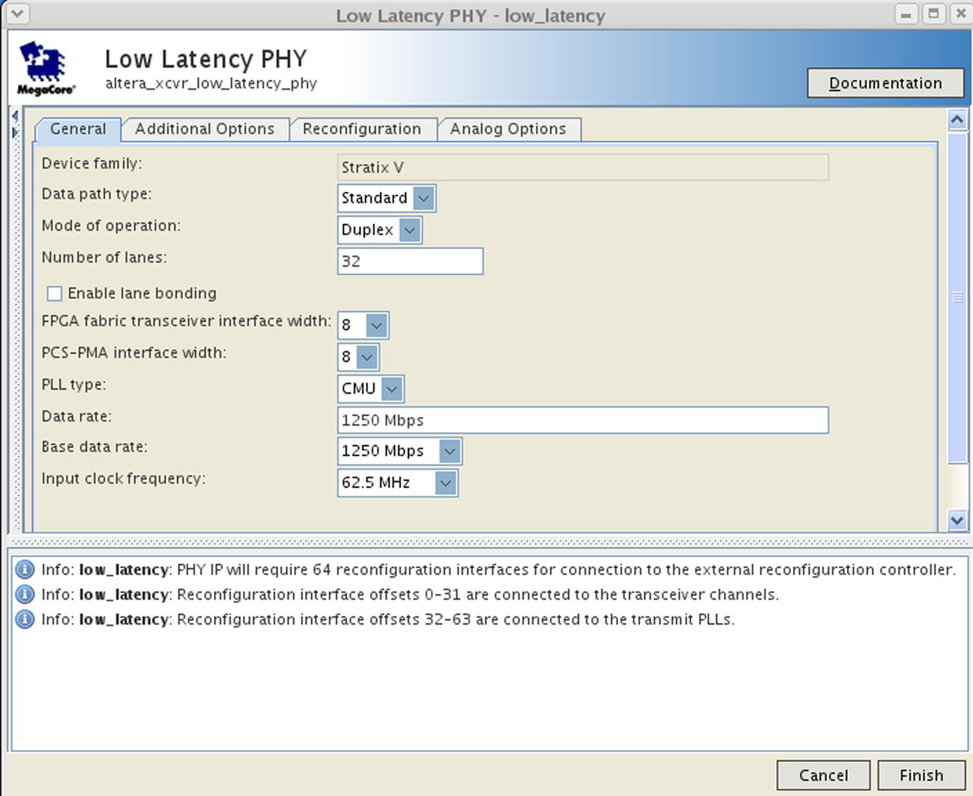
The following figure shows the Low Latency PHY IP ore GUI specifying 32 channels. The message pane indicates that reconfiguration interfaces 0–31 are for the transceiver channels and reconfiguration interfaces 32–63 are for the TX PLLs.
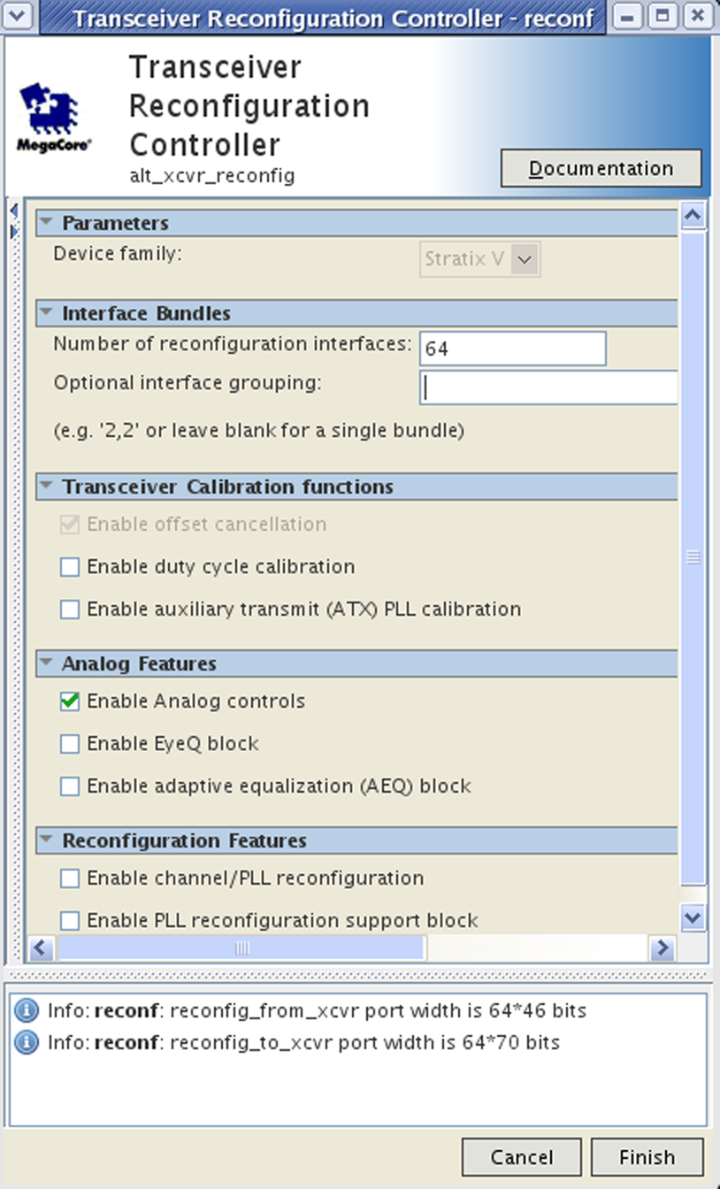
The following figure illustrates the GUI for the Transceiver Reconfiguration Controller. To connect the Low Latency PHY IP Core instance to the Transceiver Reconfiguration Controller, you would enter 64 for Number of reconfiguration interfaces. You would not need to enter any values for the Optional interface grouping parameter because all of the interfaces belong to the same transceiver PHY IP core instance.
The following figure shows a design with two transceiver PHY IP core instances, each with four channels. For this design you would enter 16 for the Number of reconfiguration interfaces and 8, 8 for the Optional interface grouping parameter.
Depending upon the transceiver PHY IP core and the parameters specified, the number of reconfiguration interfaces varies. For a single-channel, RX-only transceiver instance, there is a single reconfiguration interface. One reconfiguration interface is created for a single-channel Low Latency PHY setup as a RX only channel. Two reconfiguration interfaces are created for a single-channel Custom PHY setup as a duplex channel. The reconfiguration interfaces do not appear as separate buses, but as a single bus of concatenated reconfiguration interfaces, that grows linearly with the number of reconfiguration interfaces.
Although you must create a separate logical reconfiguration interface for each PHY IP core instance, when the Intel® Quartus® Prime software compiles your design, it reduces original number of logical interfaces by merging them. Allowing the Intel® Quartus® Prime software to merge reconfiguration interfaces gives the Fitter more flexibility in placing transceiver channels. However, the logical channel number remains the same.
You do not have to assign numbers to the reconfiguration interfaces. The logical interface numbering is determined by the order of the interfaces in the connection between the transceiver PHY IP and the Transceiver Reconfiguration Controller.