3.1.10.3. Unused Transceiver Channels in High-Speed PAM4 Mode
For PAM4 high data rate modes, there is an option to preserve unused transceiver channels in the Platform Designer IP GUI. This is exclusively for the PAM4 high data rate and not for the above two use cases.
The E-tile transceiver features a high-speed PAM4 serial transmission mode that enables effective baud rates higher than 28.9 Gbits/s. Transceiver channels that are used in high-speed PAM4 serial transmission mode must interface with the FPGA core to transmit and receive data in the parallel domain at parallel data rates that can support this high-speed serial transmission mode.
Data in the parallel domain is transferred between the FPGA core and the transceiver tile over the EMIB. This is a high-speed parallel data bus. The width of this data bus is limited by the number of physical connections between the FPGA core and the transceiver tile. Accordingly, the data transmission rate from the FPGA core to the transceiver tile is also limited by the width of the data bus and its transmission speed. For high-speed (greater than 28.9 Gbits/s) serial data transmission, a single parallel data channel of the EMIB cannot transfer parallel data fast enough to maintain the desired serial data transmission rate.
To overcome this limitation for high-speed PAM4 serial data transmission, two adjacent EMIB channels are used to transfer the parallel data between one high-speed PAM4 serial data channel and the FPGA core. The first of the two channels is referred to as the master channel and the second as the slave channel. The serial data connections for the high-speed PAM4 channel are those associated with the master channel. The slave channel serial data connections are unused in this case.
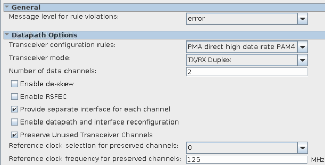
The slave channels can be protected by selecting a reference clock and its corresponding frequency in the IP GUI. The reference clock frequency must be between 125 and 500 MHz. Once this is selected, you need to provide a reference clock in the QSF file for these channels.
Generic QSF assignment:
set_location_assignment <CLK_PIN_NAME> -to <REFCLK_PORT_NAME>
set_instance_assignment -name HSSI_PARAMETER "refclk_divider_use_as_bti_clock=true" -to <REFCLK_PORT_NAME>
set_instance_assignment -name HSSI_PARAMETER "refclk_divider_input_freq=<frequency in Hz>" -to <REFCLK_PORT_NAME>
In below example, refclk1ct is the name used in the top-level design for the reference clock used for the mission mode channels. The QSF assignments specify that the other two reference clocks (refclk_preserve_ch1 and refclk_preserve_ch2), which are on different tiles (specified by the pin placement), are used to preserve channel protection.
In this instance, refclk_preserve_ch1 is in the same tile as refclk1ct, and it is used as the reference clock for the protecting slave channels in the high data rate PAM4 design.
refclk_preserve_ch2 is on another tile, and it is used as the reference clock for the unused channels in that tile that are not instantiated in the logical netlist.
Example for preserving the two slave PAM4 channels shown in the GUI above:
set_location_assignment PIN_AB43 -to refclk1ct
set_location_assignment PIN_AA40 -to refclk_preserve_ch1 // refclk_preserve_ch1 is used to protect the slave channels
set_instance_assignment -name HSSI_PARAMETER "refclk_divider_use_as_bti_clock=TRUE" -to refclk_preserve_ch1
set_instance_assignment -name HSSI_PARAMETER "refclk_divider_input_freq=1250000000" -to refclk_preserve_ch1