External Memory Interface Handbook Volume 3: Reference Material: For UniPHY-based Device Families
3.3. MPFE Signal Descriptions
| Signal |
Direction |
Description |
|---|---|---|
| avl_<signal_name>_# (1) |
— |
Local interface signals. |
| mp_cmd_clk_#_clk (1) |
Input |
Clock for the command FIFO buffer. (3) Follow Avalon® -MM master frequency. Maximum frequency is one-half of the interface frequency, and subject to timing closure. |
| mp_cmd_reset_n_#_reset_n (1) |
Input |
Asynchronous reset signal for command FIFO buffer. |
| mp_rfifo_clk_#_clk (2) |
Input |
Clock for the read data FIFO buffer. Follow Avalon® -MM master frequency. Maximum frequency is one-half of the interface frequency, and subject to timing closure. |
| mp_rfifo_reset_n_#_reset_n (2) |
Input |
Asynchronous reset signal for read data FIFO buffer. |
| mp_wfifo_clk_#_clk (2) |
Input |
Clock for the write data FIFO buffer. Follow Avalon® -MM master frequency. Maximum frequency is one-half of the interface frequency, and subject to timing closure. |
| mp_wfifo_reset_n_#_reset_n (2) |
Input |
Asynchronous reset signal for write data FIFO buffer. |
| bonding_in_1/2/3 |
Input |
Bonding interface input port. Connect second controller bonding output port to this port according to the port sequence. |
| bonding_out_1/2/3 |
Output |
Bonding interface output port. Connect this port to the second controller bonding intput port according to the port sequence. |
| Notes to Table:
|
||
Every input interface (command, read data, and write data) has its own clock domain. Each command port can be connected to a different clock, but the read data and write data ports associated with a command port must connect to the same clock as that command port. Each input interface uses the same reset signal as its clock.
By default, the IP generates all clock signals regardless of the MPFE settings, but all unused ports and FIFO buffers are connected to ground.
The command ports can be used only in unidirectional configurations, with either 4 write and 2 read, 3 write and 3 read, or 2 write and 4 read scenarios. For bidirectional ports, the number of clocks is reduced from 6 to a maximum of 4.
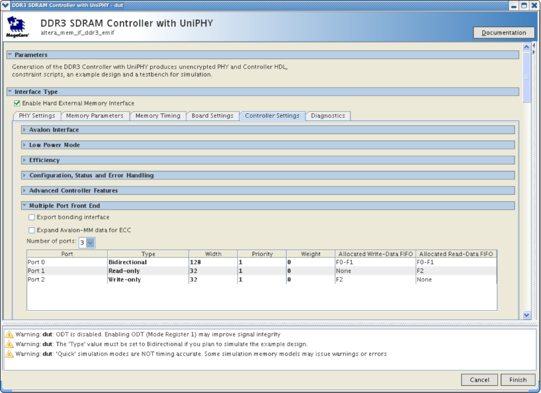
For the scenario depicted in the following figure:
- command port 0 is associated with read and write data FIFO 0 and 1
- command port 1 is associated with read data FIFO 2
- command port 2 is associated with write data FIFO 2

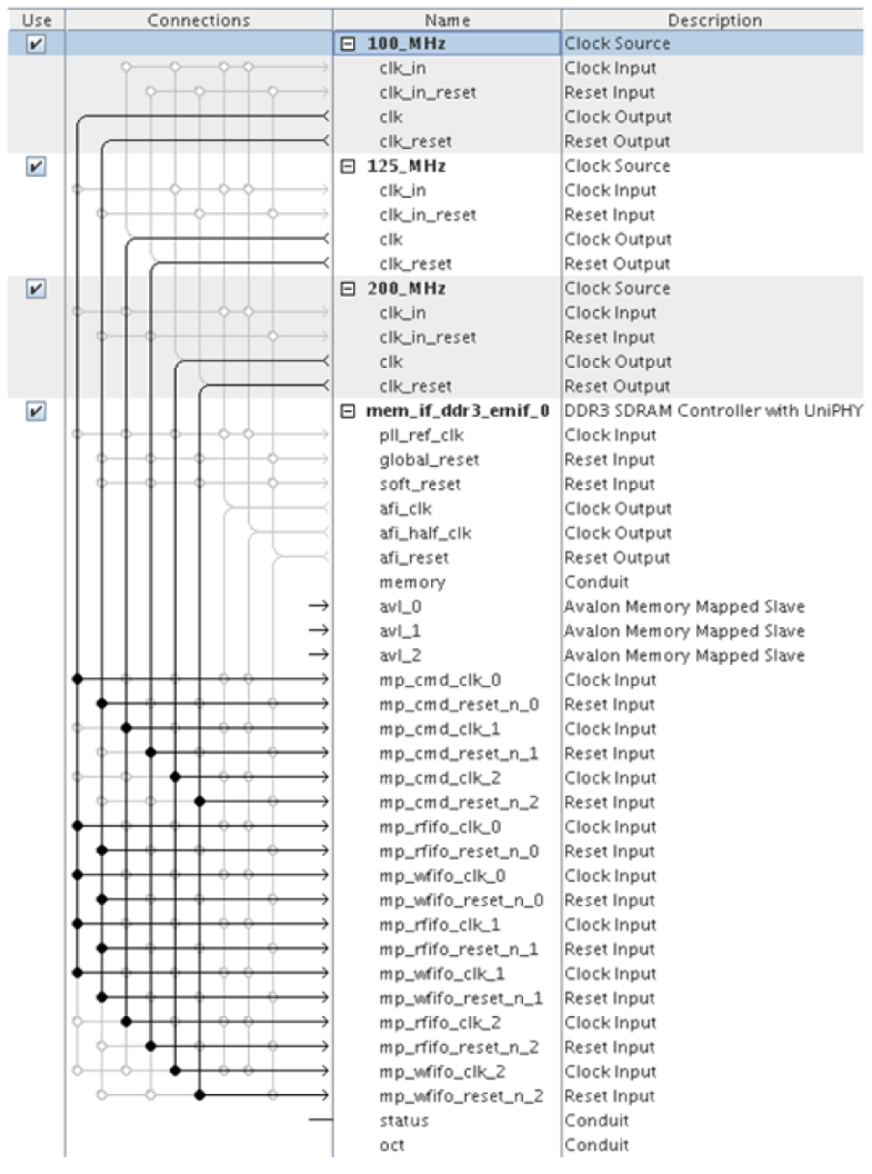
Therefore, if port 0 (avl_0) is clocked by a 100 MHz clock signal, mp_cmd_clk_0, mp_rfifo_clk_0, mp_rfifo_clk_1, mp_wfifo_clk_0, and mp_wfifo_clk_1 must all be connected to the same 100 MHz clock, as illustrated below.
