External Memory Interface Handbook Volume 3: Reference Material: For UniPHY-based Device Families
16.10.4. Applying the Traffic Generator 2.0
Testing Signal Integrity with PRBS Data Pattern
You can apply PRBS data to the data pins to help emulate an actual traffic pattern to the memory interface. The traffic generator uses a PRBS7 data pattern as the default traffic pattern on the data pins, and can support PRBS-15 and PRBS-31.
Debugging and Monitoring an Address for Reliable Data Capture
You can send a single write followed by multiple reads to a specific address to help debug and monitor a specific address for reliable data capture. You can do this with the following settings:
- Writes per block: 1
- Reads per block: 1
- Write repeats: 1
- Read repeats: 1 to 255
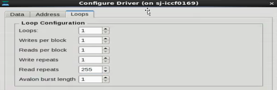
If you specify a Loops value greater than 1, every block of write and multiple read transactions will follow the same pattern. If there is a specific address to which this transaction must be issued, you should specify that address in the Start address field on the Address tab, with the Sequential address mode selected.
Accessing Large Sections of Memory
The maximum number of unique addresses that can be written to in one block is 4094. Using the maximum Loops value of 4095, the address range that can be supported in one test is equal to the number of loops multiplied by the number of writes per block. Further address expansion can be achieved by changing the Start address value appropriately and reissuing the tests.
To continue addressing sections of the memory beyond the address range that can be specified in one set of toolkit configurations, you can incrementally access the next set of addresses in the memory by changing the Start address value.
For example, in a memory where row address width is 15, bank address width is 3 and column address width is 10, the total number of address locations to be accessed is: 2 (row address width) x (bank address width x 2 (column address width)). The maximum number of address locations that can be accessed is limited by the width of the internal address bus, which is 25 bits wide.
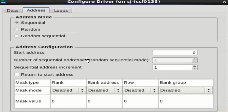
For the example described above, you must set the following values on the Address tab:
- Select the Sequential address mode.
- Set the Start address to 0x00.
- Ensure that you do not select Return to start addess.
- Ensure that you disable address masking for rank, row, bank, and bank group.
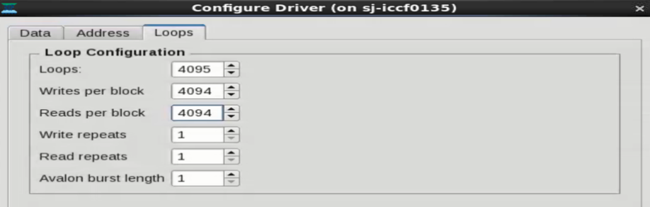
You must also set the following values on the Loops tab:
- Set Loops to the maximun value of 4095.
- Set Writes per block to the maximum value of 4094.
- Set Reads per block to the maximum value of 4094.
- Set Write repeats to 1.
- Set Read repeats to 1.
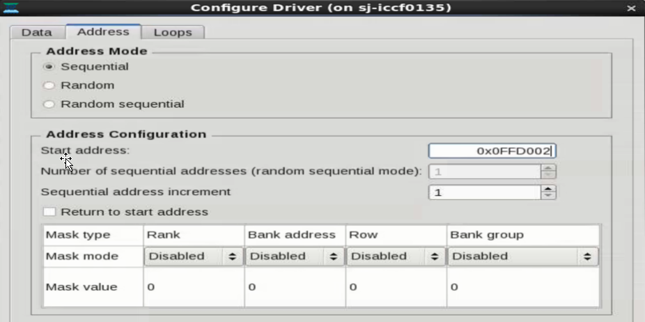
Each iteration can access a maximum of 4095 x 4094 locations (16,764,930 address locations i.e. Address ranging from 000_0000’h to FF_D001’h). To access the next 4095 x 4094 locations, the same settings as above must be repeated, except for the Start address value, whichmust be set to a hex value of 16,764,931 i.e. FF_D002. The same process can be repeated to further access memory locations inside the memory. The maximum value supported is 25’h 1FF_FFFF which is the equivalent of 33,554,432 locations inside the memory.