Quartus® Prime Standard Edition User Guide: Design Compilation
2.6.2. Design Partition Planner
To view a design and create design partitions in the Design Partition Planner, you must first compile the design, or perform Analysis & Synthesis. In the Design Partition Planner, the design appears as a single top-level design block, with lower-level instances displayed as color-specific boxes.
In the Design Partition Planner, you can show connectivity between blocks and extract instances from the top-level design block. When you extract entities, connection bundles are drawn between entities, showing the number of connections existing between pairs of entities. When you have extracted a design block that you want to set as a design partition, right-click that design block, and then click Create Design Partition.
The Design Partition Planner also has an auto-partition feature that creates partitions based on the size and connectivity of the hierarchical design blocks. You can right-click the design block you want to partition (such as the top-level design hierarchy), and then click Auto-Partition Children. You can then analyze and adjust the partition assignments as required.
The figure shows the Design Partition Planner after making a design partition assignment to one instance and dragging another instance away from the top-level block within the same partition (two design blocks in the pale blue shaded box). The figure shows the connections between each partition and information about the size of each design instance.
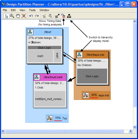
You can switch between connectivity display mode and hierarchical display mode, to examine the view-only hierarchy display. You can also remove the connection lines between partitions and I/O banks by turning off Display connections to I/O banks, or use the settings on the Connection Counting tab in the Bundle Configuration dialog box to adjust how the connections are counted in the bundles.
To optimize design performance, confine failing paths within individual design partitions so that there are no failing paths passing between partitions. In the top-level entity, child entities that contain failing paths are marked by a small red dot in the upper right corner of the entity box.
To view the critical timing paths from a timing analyzer report, first perform a timing analysis on your design, and then in the Design Partition Planner, click Show Timing Data on the View menu.