18.2. Clipper IP Parameters
| Parameter | Values | Description |
|---|---|---|
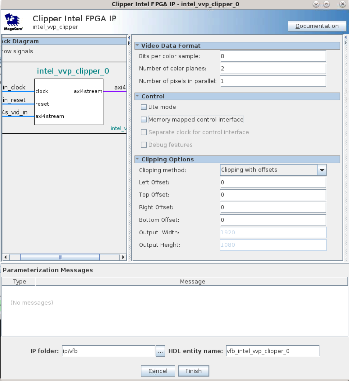
| Video Data Format | ||
| Bits per color sample | 8 to 16 | Select the number of bits per color sample. |
| Number of color planes | 1 to 4 | Select the number of color planes per pixel. |
| Number of pixels in parallel | 1 to 8 | Select the number of pixels in parallel. |
| Control | ||
| Lite mode | On or off | Turn on to use the lite variant of the Intel FPGA Streaming Video protocol. |
| Memory-mapped control interface | On or off | Turn on to specify clipping offsets using the Avalon memory-mapped interface. You must have the Avalon memory-mapped control agent interface if you turn on Lite mode. |
| Separate clock for control interface | On or off | Turn on for a separate clock for the control interface. |
| Debug features | On or off | Turn on for debugging features (not applicable when you turn on Lite mode). |
| Clipping options | ||
| Clipping method | Clipping with offsets or Clipping with output dimensions | Specify the clipping area as offsets from the edge of the input area or as a fixed rectangle. |
Left offset |
0 to 16383 | For clips of fixed dimensions, specify the x coordinate for the left edge of the clipping rectangle. 0 is the left edge of the input area. The left and right offset values must be less than or equal to the input image width. |
Top offset 45 |
0 to 16383 | For clips of fixed dimensions, specify the x coordinate for the top edge of the clipping rectangle. 0 is the top edge of the input area. The top and bottom offset values must be less than or equal to the input image height. |
Right offset 45 |
0 to 16383 | For clips of fixed dimensions, use this parameter to specify the x coordinate for the right edge of the clipping rectangle. 0 is the right edge of the input area. The left and right offset values must be less than or equal to the input image width. |
Bottom offset 45 |
0to 16383 | For clips of fixed dimensions, specify the x coordinate for the bottom edge of the clipping rectangle. 0 is the bottom edge of the input area. The top and bottom offset values must be less than or equal to the input image height. |
Output width |
1 to 16384 | For clips of fixed dimensions, specify the width of the clipping rectangle. |
Output height 46 |
1 to 16384 | For clips of fixed dimensions, specify the height of the clipping rectangle. |
Not applicable when you turn on the memory-mapped control interface or when you select Clipping with output dimensions
Not applicable when you turn on the memory-mapped control interface or when you select Clipping with offsets.