1. About the Video and Vision Processing Suite
2. Getting Started with the Video and Vision Processing IPs
3. Video and Vision Processing IPs Functional Description
4. Video and Vision Processing IP Interfaces
5. Video and Vision Processing IP Registers
6. Video and Vision Processing IPs Software Programming Model
7. Protocol Converter IP
8. 1D LUT IP
9. 3D LUT IP
10. Adaptive Noise Reduction IP
11. Advanced Test Pattern Generator IP
12. AXI-Stream Broadcaster IP
13. Bits per Color Sample Adapter IP
14. Black Level Correction IP
15. Black Level Statistics IP
16. Chroma Key IP
17. Chroma Resampler IP
18. Clipper IP
19. Clocked Video Input IP
20. Clocked Video to Full-Raster Converter IP
21. Clocked Video Output IP
22. Color Plane Manager IP
23. Color Space Converter IP
24. Defective Pixel Correction IP
25. Deinterlacer IP
26. Demosaic IP
27. FIR Filter IP
28. Frame Cleaner IP
29. Full-Raster to Clocked Video Converter IP
30. Full-Raster to Streaming Converter IP
31. Genlock Controller IP
32. Generic Crosspoint IP
33. Genlock Signal Router IP
34. Guard Bands IP
35. Histogram Statistics IP
36. Interlacer IP
37. Mixer IP
38. Pixels in Parallel Converter IP
39. Scaler IP
40. Stream Cleaner IP
41. Switch IP
42. Text Box IP
43. Tone Mapping Operator IP
44. Test Pattern Generator IP
45. Unsharp Mask IP
46. Video and Vision Monitor Intel FPGA IP
47. Video Frame Buffer IP
48. Video Frame Reader Intel FPGA IP
49. Video Frame Writer Intel FPGA IP
50. Video Streaming FIFO IP
51. Video Timing Generator IP
52. Vignette Correction IP
53. Warp IP
54. White Balance Correction IP
55. White Balance Statistics IP
56. Design Security
57. Document Revision History for Video and Vision Processing Suite User Guide
31.4.1. Achieving Genlock Controller Free Running (for Initialization or from Lock to Reference Clock N)
31.4.2. Locking to Reference Clock N (from Genlock Controller IP free running)
31.4.3. Setting the VCXO hold over
31.4.4. Restarting the Genlock Controller IP
31.4.5. Locking to Reference Clock N New (from Locking to Reference Clock N Old)
31.4.6. Changing to Reference Clock or VCXO Base Frequencies (switch between p50 and p59.94 video formats and vice-versa)
31.4.7. Disturbing a Reference Clock (a cable pull)
23.2. Color Space Converter IP Parameters
| Parameter | Value | Description |
|---|---|---|
| Control Settings | ||
| Memory-mapped control interface | On or off | Turn on to specify Color Space Converter register values using the Avalon memory-mapped interface. |
| Separate clock for control interface | On or off | Turn on for a separate clock for the control interface. |
| Debug features | On or off | Turn on for debugging features (not applicable for lite mode). |
| Pipeline ready signals | On or off | Turn on to pipeline ready signals, which helps with improving Fmax. |
| Video Data Format | ||
| Lite mode | On or off | Turn on to operate the Color Space Converter in lite mode. |
| Input bits per color sample | 8 to 16 | Select the number of input bits per color sample. |
| Output bits per color sample | 8 to 16 | Select the number of output bits per color sample. |
| Number of pixels in parallel | 1 to 8 | Select the number of pixels in parallel. |
| Output Color space | RGB, YCbCr, or MONO | Only applies if Memory-mapped control interface and Lite mode are off. Use this to set the color space field value of outgoing image information packets. It does not affect the algorithmic values, only the metadata. |
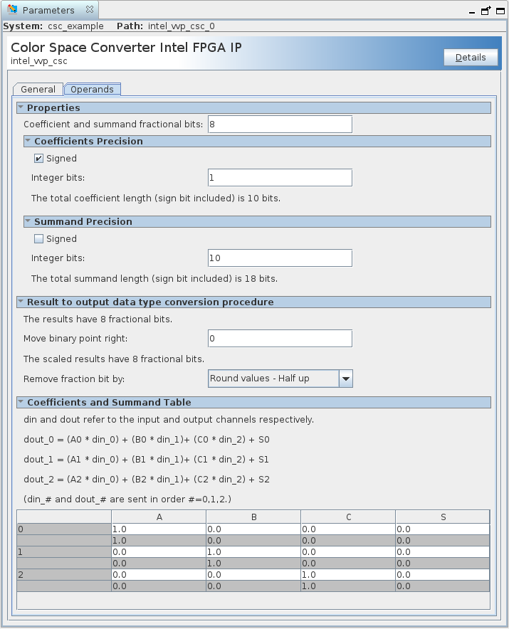
| Parameter | Allowed range | Description |
|---|---|---|
| Properties | ||
| Coefficient and summand fractional bits | 0 to 24 | Specify the number of fraction bits for the fixed-point type to store the coefficients and summands. |
| Coefficient precision: Signed | On or Off | Turn on to set the fixed-point type to store the constant coefficients as having a sign bit. |
| Coefficient precision: Integer bits | 0 to 16 | Specifies the number of integer bits for the fixed-point type to store the constant coefficients. |
| Summand precision: Signed | On or Off | Turn on to set the fixed-point type to store the constant summands as having a sign bit. |
| Summand precision: Integer bits | 0 to 20 | Specify the number of integer bits for the fixed-point type used to store the constant summands. |
| Result to output data type conversion | ||
| Move binary point right | -16 to +16 |
Specify the number of places by which to move the binary point to the right. Negative numbers indicate moving the binary point to the left. |
| Remove fraction bits by |
|
Select the method of discarding fraction bits resulting from the calculation. |
Coefficients and Summand Table A0, B0, C0, S0 A1, B1, C1, S1 A2, B2, C2, S2 |
12 fixed-point values | Only when you turn off Memory-mapped control interface. Each coefficient or summand is represented by a white cell with a gray cell underneath. The value in the white cell is the desired value and is editable. The value in the gray cell is the actual value, determined by the fixed-point type specified. The gray cells are not editable. You can create a custom coefficient and summand set by specifying one fixed-point value for each entry. |
Figure 68. Color Space Converter General TabThe figure also shows the presets
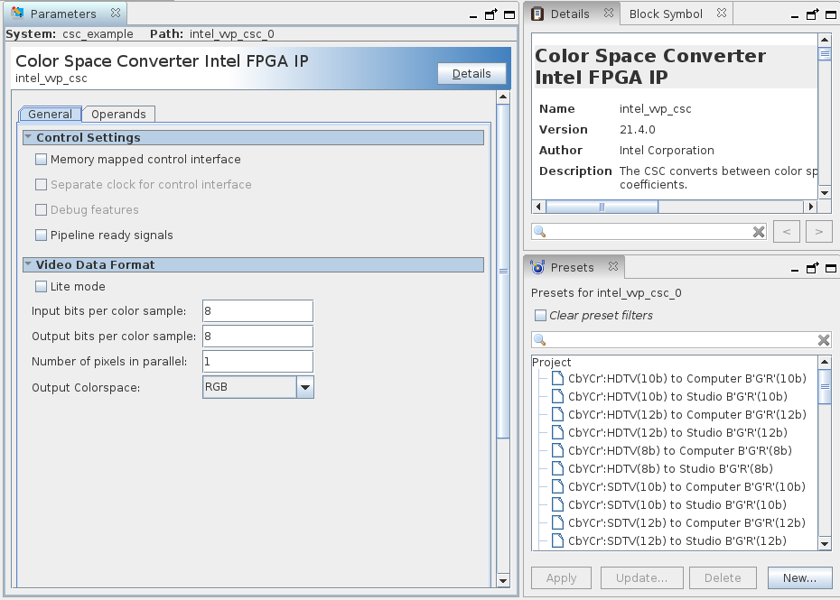
Figure 69. Color Space Converter GUI Operands Tab