PHY Lite for Parallel Interfaces Intel® FPGA IP User Guide
A newer version of this document is available. Customers should click here to go to the newest version.
This design example provides you a synthesizable system capable to perform dynamic calibration for PHY Lite for Parallel Interfaces IP core in Intel® Arria® 10 and Intel® Cyclone® 10 GX devices.
Features
- Perform dynamic reconfiguration using Avalon controller
- Read and write transactions monitoring
- Delay values monitoring
Software Requirements
- Intel® Quartus® Prime software
- Active-HDL, ModelSim* - Intel® FPGA Edition, or VCS Simulator
Functional Description
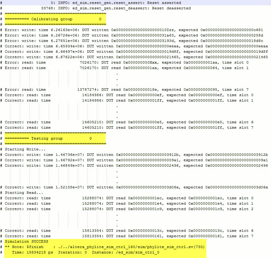
This design example introduces the cfg_ctrl and avl_ctrl blocks, which work with the sim_ctrl module to demonstrate the basic functionality of the PHY Lite for Parallel Interfaces IPs Avalon memory-mapped based reconfiguration. The agent is also modified to insert delays on the data and clocks, which the new modules will compensate for.
NOTE: The cfg_ctrl module performs a simplistic reconfiguration of the interface that stops at the first working delay values. The design example only support simulation. A robust calibration algorithm should sweep over the entire valid range of delays to choose the correct value for the application.
| Component | Description |
|---|---|
| ref_clk_gen | Generates clock to reset_gen, PHY Lite for Parallel Interfaces ADDR/CMD (ref_clk), and PHY Lite for Parallel Interfaces DUT (ref_clk) blocks. |
| reset_gen | Generates reset to PHY Lite for Parallel Interfaces ADDR/CMD and PHY Lite for Parallel Interfaces DUT blocks. |
| sim_ctrl |
|
| Driver | Generates strobe and data for each group and to PHY Lite for Parallel Interfaces_DUT block. |
| PHY Lite for Parallel Interfaces ADDR/CMD | Passing read/write commands and command clock from sim_ctrl to Agent. |
| Agent | FIFO to store data from PHY Lite for Parallel Interfaces DUT and side read/write data from sim_ctrl block. |
| cfg_ctrl | This is configuration control block which performs read and write delay calibration before test begin. The calibration results is passed to the PHY Lite for Parallel Interfaces DUT through Avalon Controller. Contains 4 FSMs:
|
| avl_ctrl | The Avalon controller is used to perform address translation to store delay settings from the calibration done by cfg_ctrl block. |
Generate the Dynamic Reconfiguration with Configuration Control Module Design Example
- In Intel® Quartus® Prime software, instantiate PHY Lite for Parallel Interfaces IP core.
- Customize parameter settings per your requirement and turn on the Use dynamic reconfiguration option.
- Click Generate Example Design. Specify a directory name to generate the design example.
- To generate Verilog or mixed-language simulation files, go to the design example directory and run the following script in Nios II Command Shell.
quartus_sh -t make_sim_design.tcl VERILOG - To generate VHDL simulation files, go to the design example directory and run the following script in Nios II Command Shell.
quartus_sh -t make_sim_design.tcl VHDL
Run the Dynamic Reconfiguration with Configuration Control Design Example
Follow these steps to compile and simulate the design:
- Change the working directory to <Example Design>\sim\ed_sim\sim\<Simulator> .
- Run the simulation script for the simulator of your choice. Refer to the table below.
Simulator Working Directory Steps Modelsim <Example Design>\sim\ed_sim\sim\mentor - do msim_setup.tcl
- ld_debug
- Add desired signals into the waveform window.
- run -all
VCS <Example Design>\sim\ed_sim\sim\synopsys\vcs - sh vcs_setup.sh
VCSMX <Example Design>\sim\ed_sim\sim\synopsys\vcsmx - sh vcsmx_setup.sh
Aldec Example Design\sim\ed_sim\sim\aldec - do rivierapro_setup.tcl
- ld_debug
- Add desired signals into the waveform window.
- run -all