External Memory Interfaces Intel® Agilex™ FPGA IP User Guide
A newer version of this document is available. Customers should click here to go to the newest version.
3.5. User-requested Reset in Intel® Agilex™ EMIF IP
| Description | |
|---|---|
| Reset-related signals | local_reset_req (input) local_reset_done (output) |
| When can user logic request a reset? | local_reset_req has effect only when local_reset_done is high. After device power-on, the local_reset_done signal transitions high upon completion of the first calibration, whether the calibration is successful or not. In subsequent calibration in user mode, local_reset_done transitions high once the calibration is completed. The local_reset_done signal takes longer to transition high in first calibration after device power-on as more operations are required to put the PHY into working state. |
| Is user-requested reset a requirement? | A user-requested reset is optional. The I/O SSM automatically ensures that the memory interface begins from a known state as part of the device power-on sequence. A user-requested reset is necessary only if the user logic must explicitly reset a memory interface after the device power-on sequence. |
| When does a user-requested reset actually happen? | Each EMIF IP instance has its own local reset request port which it must assert in order to be recalibrated. The I/O SSM continually scans the reset requests of all the EMIF interfaces that it controls, and recalibrates them when it is able to do so. The exact timing of the recalibration cannot be predicted. |
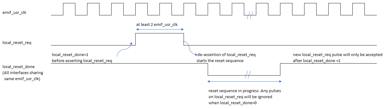
| Timing requirement and triggering mechanism. | Reset request is sent by transitioning the local_reset_req signal from low to high, then keeping the signal at the high state for a minimum of 2 EMIF core clock cycles, then transitioning the signal from high to low. local_reset_req is asynchronous in that there is no setup/hold timing to meet, but it must meet the minimum pulse width requirement of 2 EMIF core clock cycles. |
| How long can an external memory interface be kept in reset? | It is not possible to keep an external memory interface in reset indefinitely. Asserting local_reset_req high continuously has no effect as a reset request is completed by a full 0->1->0 pulse. |
| Delaying initial calibration. | Initial calibration cannot be skipped. The local_reset_done signal is driven high only after initial calibration has completed. |
| Reset scope (within an external memory interface). | Only circuits that are required to restore EMIF to power-up state are reset. Excluded from the reset sequence are the IOSSM, the IOPLL(s), the DLL(s), and the CPA. |
| Reset scope (within an I/O row). | local_reset_req is a per-interface reset. |
Method for Initiating a User-requested Reset
Step 1 - Precondition
Before asserting local_reset_req, user logic must ensure that the local_reset_done signal is high.
As part of the device power-on sequence, the local_reset_done signal automatically transitions to high upon the completion of the interface calibration sequence, regardless of whether calibration is successful or not.
Step 2 - Reset Request
After the pre-condition is satisfied, user logic can send a reset request by driving the local_cal_req signal from low to high and then low again (that is, by sending a pulse of 1).
- The low-to-high and high-to-low transitions can occur asychronously; that is, they need not happen in relation to any clock edges. However, the pulse must meet a minimum pulse width of at least 2 EMIF core clock cycles. For example, if the emif_usr_clk has a period of 4ns, then the local_reset_req pulse must last at least 8ns (that is, two emif_usr_clk periods).
- The reset request is considered complete only after the high-to-low transition. The EMIF IP does not initiate the reset sequence when the local_reset_req is simply held high.
- Additional pulses to local_reset_req are ignored until the reset sequence is completed.
Optional - Detecting local_reset_done deassertion and assertion
If you want, you can monitor the status of the local_reset_done signal to explicitly detect the status of the reset sequence.
- After the EMIF IP receives a reset request, it deasserts the local_reset_done signal. After initial power-up calibration, local_reset_done is de-asserted only in response to a user-requested reset. The reset sequence is imminent when local_reset_done has transitioned to low, although the exact timing depends on the current state of the I/O SSM. As part of the EMIF reset sequence, the core reset signal (emif_usr_reset_n, afi_reset_n) is driven low. Do not use a register reset by the core reset signal to sample local_reset_done.
- After the reset sequence has completed, local_reset_done is driven high again. local_reset_done being driven high indicates the completion of the reset sequence and the readiness to accept a new reset request; however, it does not imply that calibration was successful or that the hard memory controller is ready to accept requests. For these purposes, user logic must check signals such as afi_cal_success, afi_cal_fail, local_cal_success, local_cal_fail, and amm_ready.