External Memory Interfaces Intel® Agilex™ FPGA IP User Guide
A newer version of this document is available. Customers should click here to go to the newest version.
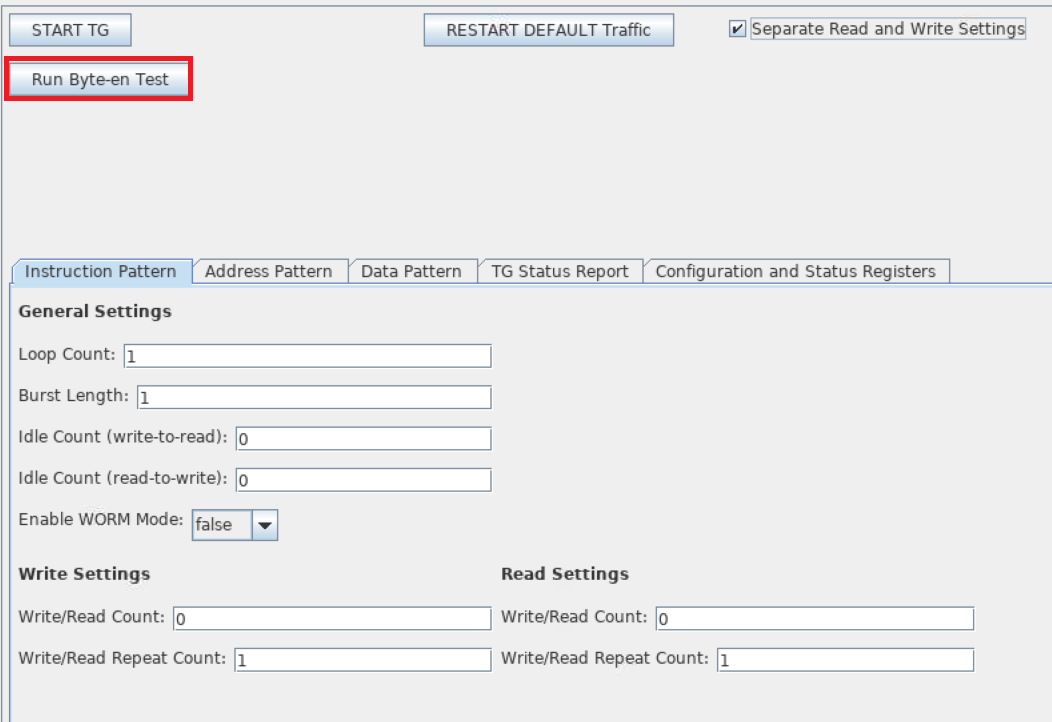
11.9.8.2. Configuring the Traffic Generator
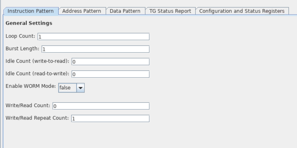
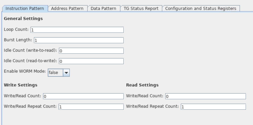
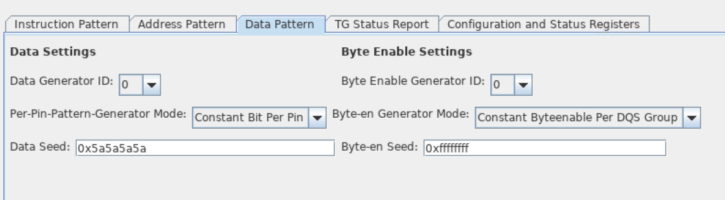
Set all the required parameters on the Instruction Pattern, Address Pattern, and Data Pattern tabs in the traffic generator interface. For information about how each setting affects the final traffic pattern, refer to the User-Configured Traffic Pattern section.
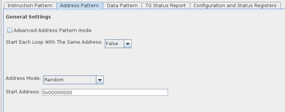
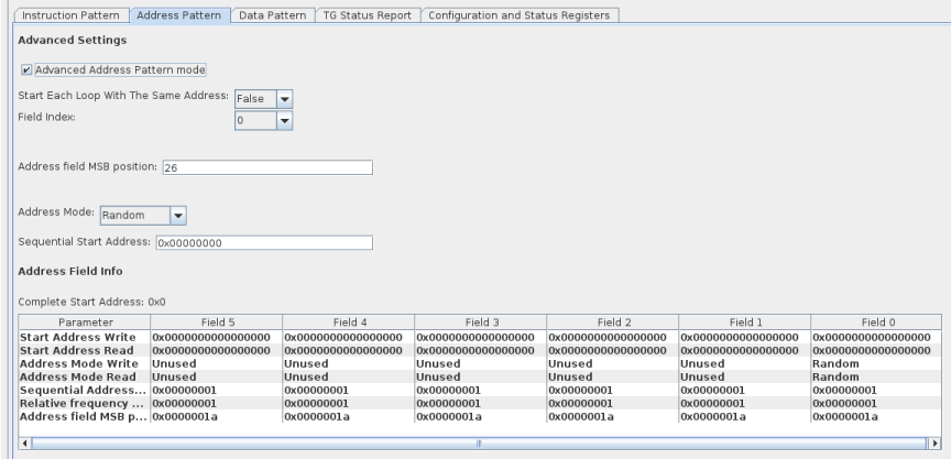
The address pattern tab can be viewed in Basic Mode or Advanced Mode. Basic Mode presents a simple method of address generation where the specified pattern affects the full address width. Basic mode lets you generate addresses randomly, sequentially, or random-sequentially from a given starting address, with a given address increment. Conversely, Advanced Mode lets you specify six independent patterns for different portions of the address, by selecting a field index to configure from the drop-down menu, and then setting the MSB position, address mode, start address, and relative frequency. Basic Mode is a subset of Advanced Mode, and the same configurations apply.
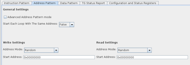
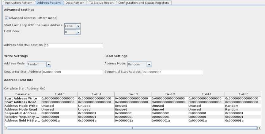
If you click Separate Read and Write Settings at the top of the dialog box, the Instruction Pattern and Address Pattern tabs display separate Write Settings parameters and Read Settings parameters, where applicable.
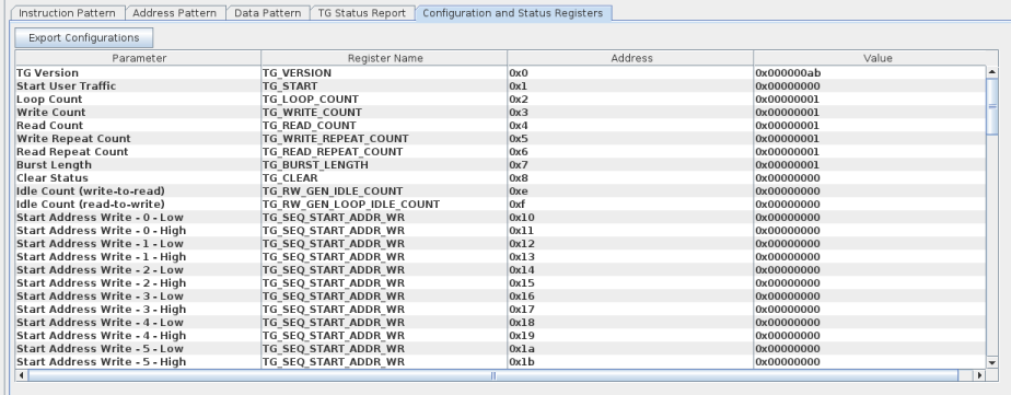
The Configurations tab shows all of the configurations available on the interface, and the values to which each is set.
Byte-enable Test
The byte-enable test consists of three stages, as follows:
- Write-only stage: 3 writes with write_data and byte-enable.
- Invert byte-enable and write_data stage: 3 writes with inverted write_data and inverted byte-enable. This stage is accomplished by writing a value of 1 to TG_INVERT_BYTEEN (symbol address 0xAC).
- Read-only stage: 3 reads and comparison of read_data with (write_data & byte-enable | ~write_data & ~byte-enable). Test byte-enable comparison is enabled by writing a value of 1 to TG_TEST_BYTEEN (symbol address 0xB8).