External Memory Interfaces Intel® Agilex™ FPGA IP User Guide
A newer version of this document is available. Customers should click here to go to the newest version.
11.9.6. Traffic Generator Status
Status Registers
The traffic generator reports status in two ways:
- ISSPs
- Configuration interface
Reading PNF Registers or ISSPs
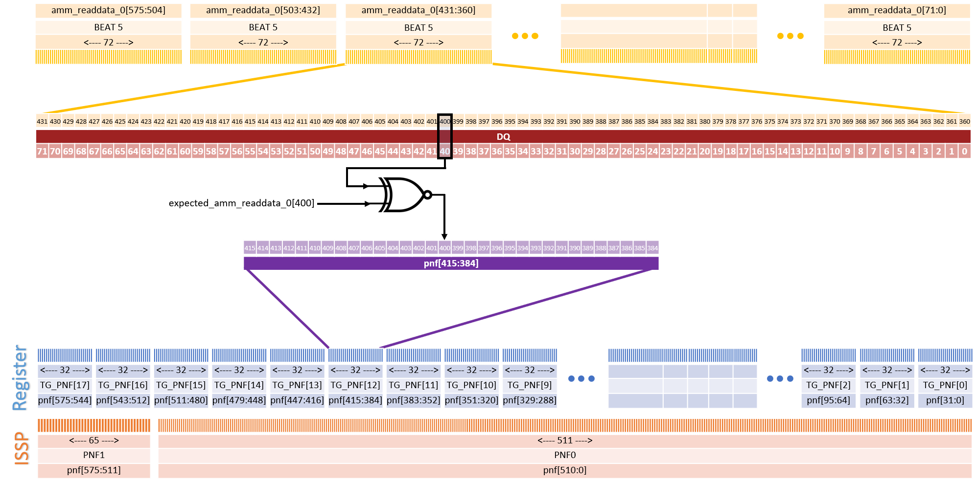
The Pass Not Fail (PNF) registers show the status for each bit that has been read on the ctrl_amm interface.
pnf[x] = ~(amm_readdata_0[x]^amm_expected_readdata_0[x])The PNF signal is “sticky”, which means that once a PNF bit is set to 0 due to a read miscompare, it does not return to a value of 1 on any consecutive reads, until the PNF is cleared. The PNF, TG_FAIL_EXPECTED_DATA, and TG_FAIL_READ_DATA registers are normally wider than a single register on the tg_cfg interface. As a result, the bus width is split up across NPNF_reg registers, where:
NPNF_reg = ceil(TG_RDATA_WIDTH / 32)To determine the address of the Nth register:
TG_PNF[NPNF_reg] = (Symbol Address of TG_PNF) + 4*NPNF_regThe maximum PNF width is 511 bits, so the bus width is split up across NPNF_ISSP ISSPs:
NPNG_ISSP = ceil(TG_RDATA_WIDTH / 511)PNF ISSPs have the index in their name, starting with PNF0.
Example:
This example assumes the following conditions:
- DQ Width: x72 (without ECC enabled)
- Memory Protocol: DDR4
- DQ/DQS: 8
- Rate: Quarter-rate
Due to the memory protocol and rate, TG_DATA_RATE_WIDTH_RATIO = 8.
Therefore TG_RDATA_WIDTH = 72 * 8 = 576. This means that there are 18 TG_PNF registers, and two PNF ISSPs (PNF0, PNF1), as illustrated below:
Clearing Failure Information Between Runs
You can set the TG_CLEAR register to clear failure information between successive runs of the traffic generator.
Configuration Error Codes
The TG_ERROR_REPORT register codes flag when the traffic pattern may be the direct cause for data mismatches. You may still choose to run the traffic pattern, despite errors. This may be useful when not looking for a passing comparison.
The following table outlines the error codes:
| Code Value | Code Name | Code Description |
|---|---|---|
| 0x1 | ERR_MORE_READS_THAN_WRITES | More read operations are scheduled than write operations. Data mismatches might occur. |
| 0x2 | ERR_BURSTLENGTH_GT_SEQ_ADDR_INCR | The Avalon® burst length exceeds the sequential address increment. Data mismatches might occur. |
| 0x4 | ERR_ADDR_DIVISIBLE_BY_GT_SEQ_ADDR_INCR | The sequential address increment is smaller than the minimum required. Data mismatches might occur. |
| 0x8 | ERR_SEQ_ADDR_INCR_NOT_DIVISIBLE | The sequential address increment is not divisible by the necessary step. Data mismatches might occur. |
| 0x10 | ERR_READ_AND_WRITE_START_ADDRS_DIFFER | The sequential address increment is not divisible by the necessary step. Data mismatches might occur. |
| 0x20 | ERR_ADDR_MODES_DIFFERENT | Read and write settings for address generation modes are different. Data mismatches might occur. |
| 0x40 | ERR_REPEATS_SET_TO_ZERO | Invalid read or write repeat count. The number of read or write repeats must be at least 1. Data mismatches might occur. |
| 0x80 | ERR_BOTH_BURST_AND_REPEAT_MODE_ACTIVE | Invalid read or write repeat count. The number of read or write repeats must be at least 1. Data mismatches might occur. |
| 0x100 | ERR_BURSTLENGTH_AND_WORD_ADDR_DIVISIBLE_FIELD_0 | The width of field 0 must be greater than the number of bits required for burst length plus the number of LSB bits for the smallest possible step. Data mismatches may occur. |
| 0x200 | ERR_RELATIVE_FREQ_ZERO | The relative frequency of a field is zero. Data mismatches may occur. |