Intel® Quartus® Prime Standard Edition User Guide: Platform Designer
ID
683364
Date
12/15/2018
Public
1. Creating a System with Platform Designer
2. Optimizing Platform Designer System Performance
3. Platform Designer Interconnect
4. Platform Designer System Design Components
5. Creating Platform Designer Components
6. Platform Designer Command-Line Utilities
7. Component Interface Tcl Reference
A. Intel® Quartus® Prime Standard Edition User Guides
1.1. Platform Designer Interface Support
1.2. Platform Designer System Design Flow
1.3. Starting or Opening a Project in Platform Designer
1.4. Viewing a Platform Designer System
1.5. Adding IP Components to a System
1.6. Connecting System Components
1.7. Specifying Interconnect Requirements
1.8. Defining Instance Parameters
1.9. Implementing Performance Monitoring
1.10. Configuring Platform Designer System Security
1.11. Upgrading Outdated IP Components
1.12. Synchronizing System Component Information
1.13. Generating a Platform Designer System
1.14. Simulating a Platform Designer System
1.15. Integrating a Platform Designer System with the Intel® Quartus® Prime Software
1.16. Managing Hierarchical Platform Designer Systems
1.17. Creating a System with Platform Designer Revision History
1.13.1. Generation Dialog Box Options
1.13.2. Specifying the Generation ID
1.13.3. Files Generated for IP Cores and Platform Designer Systems
1.13.4. Generating System Testbench Files
1.13.5. Generating Example Designs for IP Components
1.13.6. Generating the HPS IP Component System View Description File
1.13.7. Generating Header Files for Master Components
1.16.1. Adding a Subsystem to a Platform Designer System
1.16.2. Viewing and Traversing Subsystem Contents
1.16.3. Editing a Subsystem
1.16.4. Changing a Component's Hierarchy Level
1.16.5. Saving a Subsystem
1.16.6. Exporting a System as an IP Component
1.16.7. Hierarchical System Using Instance Parameters Example
2.1. Designing with Avalon® and AXI Interfaces
2.2. Using Hierarchy in Systems
2.3. Using Concurrency in Memory-Mapped Systems
2.4. Inserting Pipeline Stages to Increase System Frequency
2.5. Using Bridges
2.6. Increasing Transfer Throughput
2.7. Reducing Logic Utilization
2.8. Reducing Power Consumption
2.9. Reset Polarity and Synchronization in Platform Designer
2.10. Optimizing Platform Designer System Performance Design Examples
2.11. Optimizing Platform Designer System Performance Revision History
3.1. Memory-Mapped Interfaces
3.2. Avalon® Streaming Interfaces
3.3. Interrupt Interfaces
3.4. Clock Interfaces
3.5. Reset Interfaces
3.6. Conduits
3.7. Interconnect Pipelining
3.8. Error Correction Coding (ECC) in Platform Designer Interconnect
3.9. AMBA* 3 AXI Protocol Specification Support (version 1.0)
3.10. AMBA* 3 APB Protocol Specification Support (version 1.0)
3.11. AMBA* 4 AXI Memory-Mapped Interface Support (version 2.0)
3.12. AMBA* 4 AXI Streaming Interface Support (version 1.0)
3.13. AMBA* 4 AXI-Lite Protocol Specification Support (version 2.0)
3.14. Port Roles (Interface Signal Types)
3.15. Platform Designer Interconnect Revision History
3.1.1. Platform Designer Packet Format
3.1.2. Interconnect Domains
3.1.3. Master Network Interfaces
3.1.4. Slave Network Interfaces
3.1.5. Arbitration
3.1.6. Memory-Mapped Arbiter
3.1.7. Datapath Multiplexing Logic
3.1.8. Width Adaptation
3.1.9. Burst Adapter
3.1.10. Waitrequest Allowance Adapter
3.1.11. Read and Write Responses
3.1.12. Platform Designer Address Decoding
3.5.4.3.1. Reset Sequencer Status Register
3.5.4.3.2. Reset Sequencer Interrupt Enable Register
3.5.4.3.3. Reset Sequencer Control Register
3.5.4.3.4. Reset Sequencer Software Sequenced Reset Assert Control Register
3.5.4.3.5. Reset Sequencer Software Sequenced Reset Deassert Control Register
3.5.4.3.6. Reset Sequencer Software Direct Controlled Resets
3.5.4.3.7. Reset Sequencer Software Reset Masking
3.11.1. Burst Support
3.11.2. QoS
3.11.3. Regions
3.11.4. Write Response Dependency
3.11.5. AWCACHE and ARCACHE
3.11.6. Width Adaptation and Data Packing in Platform Designer
3.11.7. Ordering Model
3.11.8. Read and Write Allocate
3.11.9. Locked Transactions
3.11.10. Memory Types
3.11.11. Mismatched Attributes
3.11.12. Signals
3.14.1. AXI Master Interface Signal Types
3.14.2. AXI Slave Interface Signal Types
3.14.3. AMBA* 4 AXI Master Interface Signal Types
3.14.4. AMBA* 4 AXI Slave Interface Signal Types
3.14.5. AMBA* 4 AXI-Stream Master and Slave Interface Signal Types
3.14.6. ACE-Lite Interface Signal Roles
3.14.7. APB Interface Signal Types
3.14.8. Avalon® Memory-Mapped Interface Signal Roles
3.14.9. Avalon® Streaming Interface Signal Roles
3.14.10. Avalon® Clock Source Signal Roles
3.14.11. Avalon® Clock Sink Signal Roles
3.14.12. Avalon® Conduit Signal Roles
3.14.13. Avalon® Tristate Conduit Signal Roles
3.14.14. Avalon® Tri-State Slave Interface Signal Types
3.14.15. Avalon® Interrupt Sender Signal Roles
3.14.16. Avalon® Interrupt Receiver Signal Roles
4.1. Bridges
4.2. Error Response Slave
4.3. Tri-State Components
4.4. Test Pattern Generator and Checker Cores
4.5. Avalon® -ST Splitter Core
4.6. Avalon® -ST Delay Core
4.7. Avalon® -ST Round Robin Scheduler
4.8. Avalon® Packets to Transactions Converter
4.9. Avalon® -ST Streaming Pipeline Stage
4.10. Streaming Channel Multiplexer and Demultiplexer Cores
4.11. Single-Clock and Dual-Clock FIFO Cores
4.12. Platform Designer System Design Components Revision History
4.4.4.1. data_source_reset()
4.4.4.2. data_source_init()
4.4.4.3. data_source_get_id()
4.4.4.4. data_source_get_supports_packets()
4.4.4.5. data_source_get_num_channels()
4.4.4.6. data_source_get_symbols_per_cycle()
4.4.4.7. data_source_get_enable()
4.4.4.8. data_source_set_enable()
4.4.4.9. data_source_get_throttle()
4.4.4.10. data_source_set_throttle()
4.4.4.11. data_source_is_busy()
4.4.4.12. data_source_fill_level()
4.4.4.13. data_source_send_data()
4.4.5.1. data_sink_reset()
4.4.5.2. data_sink_init()
4.4.5.3. data_sink_get_id()
4.4.5.4. data_sink_get_supports_packets()
4.4.5.5. data_sink_get_num_channels()
4.4.5.6. data_sink_get_symbols_per_cycle()
4.4.5.7. data_sink_get_enable()
4.4.5.8. data_sink_set enable()
4.4.5.9. data_sink_get_throttle()
4.4.5.10. data_sink_set_throttle()
4.4.5.11. data_sink_get_packet_count()
4.4.5.12. data_sink_get_error_count()
4.4.5.13. data_sink_get_symbol_count()
4.4.5.14. data_sink_get_exception()
4.4.5.15. data_sink_exception_is_exception()
4.4.5.16. data_sink_exception_has_data_error()
4.4.5.17. data_sink_exception_has_missing_sop()
4.4.5.18. data_sink_exception_has_missing_eop()
4.4.5.19. data_sink_exception_signalled_error()
4.4.5.20. data_sink_exception_channel()
5.1. Platform Designer Components
5.2. Design Phases of an IP Component
5.3. Create IP Components in the Platform Designer Component Editor
5.4. Specify IP Component Type Information
5.5. Create an HDL File in the Platform Designer Component Editor
5.6. Create an HDL File Using a Template in the Platform Designer Component Editor
5.7. Specify Synthesis and Simulation Files in the Platform Designer Component Editor
5.8. Add Signals and Interfaces in the Platform Designer Component Editor
5.9. Specify Parameters in the Platform Designer Component Editor
5.10. Declaring SystemVerilog Interfaces in _hw.tcl
5.11. User Alterable HDL Parameters in _hw.tcl
5.12. Scripting Wire-Level Expressions
5.13. Control Interfaces Dynamically with an Elaboration Callback
5.14. Control File Generation Dynamically with Parameters and a Fileset Callback
5.15. Create a Composed Component or Subsystem
5.16. Create an IP Component with Platform Designer a System View Different from the Generated Synthesis Output Files
5.17. Add Component Instances to a Static or Generated Component
5.18. Creating Platform Designer Components Revision History
5.7.1. Specify HDL Files for Synthesis in the Platform Designer Component Editor
5.7.2. Analyze Synthesis Files in the Platform Designer Component Editor
5.7.3. Name HDL Signals for Automatic Interface and Type Recognition in the Platform Designer Component Editor
5.7.4. Specify Files for Simulation in the Component Editor
5.7.5. Include an Internal Register Map Description in the .svd for Slave Interfaces Connected to an HPS Component
6.1. Run the Platform Designer Editor with qsys-edit
6.2. Scripting IP Core Generation
6.3. Display Available IP Components with ip-catalog
6.4. Create an .ipx File with ip-make-ipx
6.5. Generate Simulation Scripts
6.6. Generate a Platform Designer System with qsys-script
6.7. Platform Designer Scripting Command Reference
6.8. Platform Designer Scripting Property Reference
6.9. Platform Designer Command-Line Interface Revision History
6.7.1.1. create_system
6.7.1.2. export_hw_tcl
6.7.1.3. get_device_families
6.7.1.4. get_devices
6.7.1.5. get_module_properties
6.7.1.6. get_module_property
6.7.1.7. get_project_properties
6.7.1.8. get_project_property
6.7.1.9. load_system
6.7.1.10. save_system
6.7.1.11. set_module_property
6.7.1.12. set_project_property
6.7.2.1. get_composed_connections
6.7.2.2. get_composed_connection_parameter_value
6.7.2.3. get_composed_connection_parameters
6.7.2.4. get_composed_instance_assignment
6.7.2.5. get_composed_instance_assignments
6.7.2.6. get_composed_instance_parameter_value
6.7.2.7. get_composed_instance_parameters
6.7.2.8. get_composed_instances
6.7.3.1. add_instance
6.7.3.2. apply_instance_preset
6.7.3.3. create_ip
6.7.3.4. add_component
6.7.3.5. duplicate_instance
6.7.3.6. enable_instance_parameter_update_callback
6.7.3.7. get_instance_assignment
6.7.3.8. get_instance_assignments
6.7.3.9. get_instance_documentation_links
6.7.3.10. get_instance_interface_assignment
6.7.3.11. get_instance_interface_assignments
6.7.3.12. get_instance_interface_parameter_property
6.7.3.13. get_instance_interface_parameter_value
6.7.3.14. get_instance_interface_parameters
6.7.3.15. get_instance_interface_port_property
6.7.3.16. get_instance_interface_ports
6.7.3.17. get_instance_interface_properties
6.7.3.18. get_instance_interface_property
6.7.3.19. get_instance_interfaces
6.7.3.20. get_instance_parameter_property
6.7.3.21. get_instance_parameter_value
6.7.3.22. get_instance_parameter_values
6.7.3.23. get_instance_parameters
6.7.3.24. get_instance_port_property
6.7.3.25. get_instance_properties
6.7.3.26. get_instance_property
6.7.3.27. get_instances
6.7.3.28. is_instance_parameter_update_callback_enabled
6.7.3.29. remove_instance
6.7.3.30. set_instance_parameter_value
6.7.3.31. set_instance_parameter_values
6.7.3.32. set_instance_property
6.7.4.1. add_connection
6.7.4.2. auto_connect
6.7.4.3. get_connection_parameter_property
6.7.4.4. get_connection_parameter_value
6.7.4.5. get_connection_parameters
6.7.4.6. get_connection_properties
6.7.4.7. get_connection_property
6.7.4.8. get_connections
6.7.4.9. remove_connection
6.7.4.10. remove_dangling_connections
6.7.4.11. set_connection_parameter_value
6.7.5.1. add_interface
6.7.5.2. get_exported_interface_sysinfo_parameter_value
6.7.5.3. get_exported_interface_sysinfo_parameters
6.7.5.4. get_interface_port_property
6.7.5.5. get_interface_ports
6.7.5.6. get_interface_properties
6.7.5.7. get_interface_property
6.7.5.8. get_interfaces
6.7.5.9. get_port_properties
6.7.5.10. remove_interface
6.7.5.11. set_interface_port_property
6.7.5.12. set_interface_property
6.7.7.1. auto_assign_base_addresses
6.7.7.2. auto_assign_irqs
6.7.7.3. auto_assign_system_base_addresses
6.7.7.4. get_interconnect_requirement
6.7.7.5. get_interconnect_requirements
6.7.7.6. get_parameter_properties
6.7.7.7. lock_avalon_base_address
6.7.7.8. send_message
6.7.7.9. set_interconnect_requirement
6.7.7.10. set_use_testbench_naming_pattern
6.7.7.11. unlock_avalon_base_address
6.7.7.12. get_testbench_dutname
6.7.7.13. get_use_testbench_naming_pattern
6.8.1. Connection Properties
6.8.2. Design Environment Type Properties
6.8.3. Direction Properties
6.8.4. Element Properties
6.8.5. Instance Properties
6.8.6. Interface Properties
6.8.7. Message Levels Properties
6.8.8. Module Properties
6.8.9. Parameter Properties
6.8.10. Parameter Status Properties
6.8.11. Parameter Type Properties
6.8.12. Port Properties
6.8.13. Project Properties
6.8.14. System Info Type Properties
6.8.15. Units Properties
6.8.16. Validation Properties
6.8.17. Interface Direction
6.8.18. File Set Kind
6.8.19. Access Type
6.8.20. Instantiation HDL File Properties
6.8.21. Instantiation Interface Duplicate Type
6.8.22. Instantiation Interface Properties
6.8.23. Instantiation Properties
6.8.24. Port Properties
6.8.25. VHDL Type
7.1.1.1. add_interface
7.1.1.2. add_interface_port
7.1.1.3. get_interfaces
7.1.1.4. get_interface_assignment
7.1.1.5. get_interface_assignments
7.1.1.6. get_interface_ports
7.1.1.7. get_interface_properties
7.1.1.8. get_interface_property
7.1.1.9. get_port_properties
7.1.1.10. get_port_property
7.1.1.11. set_interface_assignment
7.1.1.12. set_interface_property
7.1.1.13. set_port_property
7.1.1.14. set_interface_upgrade_map
7.1.4.1. add_documentation_link
7.1.4.2. get_module_assignment
7.1.4.3. get_module_assignments
7.1.4.4. get_module_ports
7.1.4.5. get_module_properties
7.1.4.6. get_module_property
7.1.4.7. send_message
7.1.4.8. set_module_assignment
7.1.4.9. set_module_property
7.1.4.10. add_hdl_instance
7.1.4.11. package
7.1.5.1. add_instance
7.1.5.2. add_connection
7.1.5.3. get_connections
7.1.5.4. get_connection_parameters
7.1.5.5. get_connection_parameter_value
7.1.5.6. get_instances
7.1.5.7. get_instance_interfaces
7.1.5.8. get_instance_interface_ports
7.1.5.9. get_instance_interface_properties
7.1.5.10. get_instance_property
7.1.5.11. set_instance_property
7.1.5.12. get_instance_properties
7.1.5.13. get_instance_interface_property
7.1.5.14. get_instance_parameters
7.1.5.15. get_instance_parameter_property
7.1.5.16. get_instance_parameter_value
7.1.5.17. get_instance_port_property
7.1.5.18. set_connection_parameter_value
7.1.5.19. set_instance_parameter_value
7.1.6.1. add_fileset
7.1.6.2. add_fileset_file
7.1.6.3. set_fileset_property
7.1.6.4. get_fileset_file_attribute
7.1.6.5. set_fileset_file_attribute
7.1.6.6. get_fileset_properties
7.1.6.7. get_fileset_property
7.1.6.8. get_fileset_sim_properties
7.1.6.9. set_fileset_sim_properties
7.1.6.10. create_temp_file
7.2.1. Script Language Properties
7.2.2. Interface Properties
7.2.3. SystemVerilog Interface Properties
7.2.4. Instance Properties
7.2.5. Parameter Properties
7.2.6. Parameter Type Properties
7.2.7. Parameter Status Properties
7.2.8. Port Properties
7.2.9. Direction Properties
7.2.10. Display Item Properties
7.2.11. Display Item Kind Properties
7.2.12. Display Hint Properties
7.2.13. Module Properties
7.2.14. Fileset Properties
7.2.15. Fileset Kind Properties
7.2.16. Callback Properties
7.2.17. File Attribute Properties
7.2.18. File Kind Properties
7.2.19. File Source Properties
7.2.20. Simulator Properties
7.2.21. Port VHDL Type Properties
7.2.22. System Info Type Properties
7.2.23. Design Environment Type Properties
7.2.24. Units Properties
7.2.25. Operating System Properties
7.2.26. Quartus.ini Type Properties
2.9. Reset Polarity and Synchronization in Platform Designer
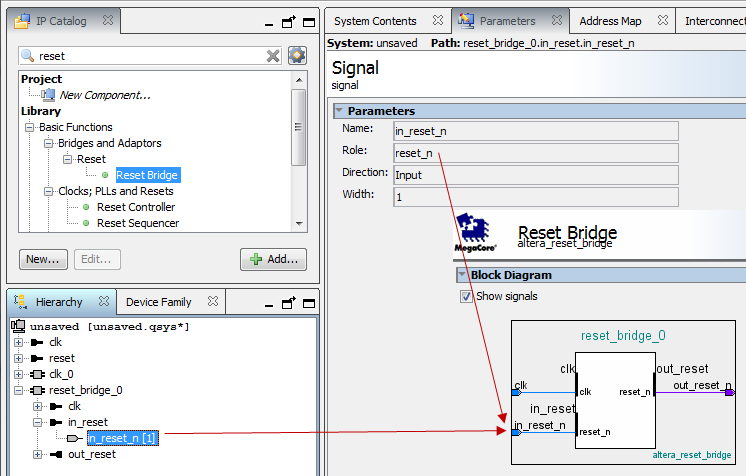
When you add a component interface with a reset signal, Platform Designer defines its polarity as reset(active-high) or reset_n (active-low).
You can view the polarity status of a reset signal by selecting the signal in the Hierarchy tab, and then view its expanded definition in the open Parameters and Block Symbol tabs. When you generate your component, Platform Designer interconnect automatically inverts polarities as needed.
Figure 70. Reset Signal (Active-High)
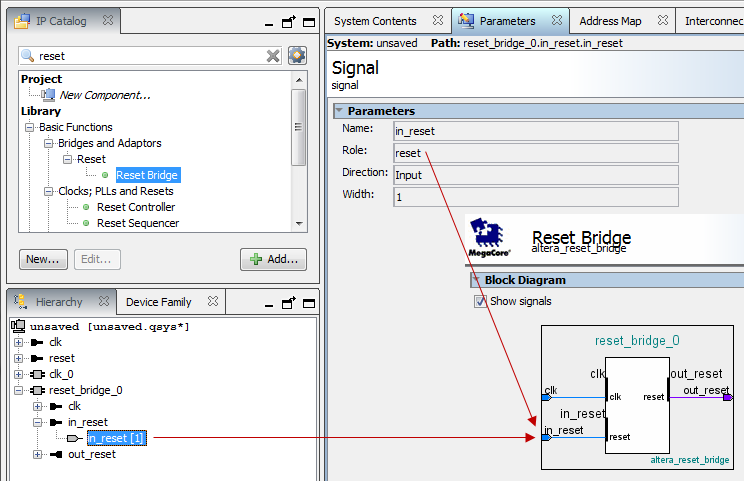
Figure 71. Reset Signal Active-Low
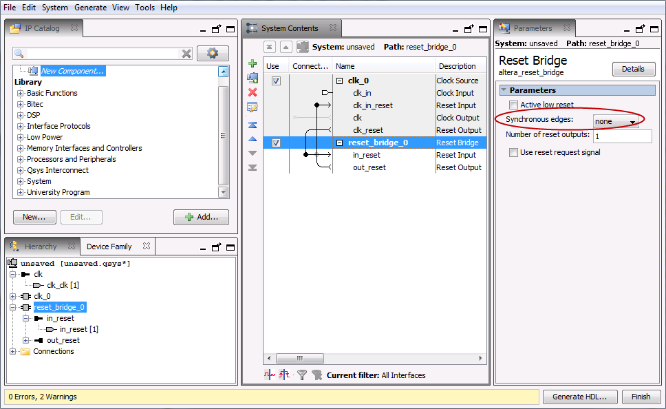
Each Platform Designer component has its own requirements for reset synchronization. Some blocks have internal synchronization and have no requirements, whereas other blocks require an externally synchronized reset. You can define how resets are synchronized in your Platform Designer system with the Synchronous edges parameter. In the clock source or reset bridge component, set the value of the Synchronous edges parameter to one of the following, depending on how the reset is externally synchronized:
- None—There is no synchronization on this reset.
- Both—The reset is synchronously asserted and deasserted with respect to the input clock.
- Deassert—The reset is synchronously asserted with respect to the input clock, and asynchronously deasserted.
Figure 72. Synchronous Edges Parameter
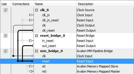
You can combine multiple reset sources to reset a particular component.
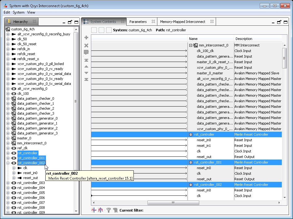
Figure 73. Combine Multiple Reset Sources
When you generate your component, Platform Designer inserts adapters to synchronize or invert resets if there are mismatches in polarity or synchronization between the source and destination. You can view inserted adapters on the Memory-Mapped Interconnect tab with the System > Show System with Platform Designer Interconnect command.
Figure 74. Platform Designer Interconnect