DSP Builder for Intel® FPGAs (Advanced Blockset): Handbook
A newer version of this document is available. Customers should click here to go to the newest version.
9.6.4. Distributed Delays in DSP Builder Designs
In this example, the Mult block has a direct feed-through simulation model, and the following SampleDelay block has a delay of 10. The Mult block has zero delay in simulation, followed by a delay of 10. In the generated hardware, DSP Builder distributes part of this 10-stage pipelining throughout the multiplier optimally, such that the Mult block has a delay (in this case, four pipelining stages) and the SampleDelay block a delay (in this case, six pipelining stages). The overall result is the same—10 pipelining stages, but if you try to match signals in the primitive subsystem against hardware, you may find DSP Builder shifts them by several cycles.
Similarly, if you have insufficient user-inserted delay to meet the required fMAX, DSP Builder automatically pipelines and balances the delays, and then corrects the cycle-accuracy of the primitive subsystem as a whole, by delaying the output signals in simulation by the appropriate number of cycles at the ChannelOut block.
If you specify no pipelining, the simulation design example for the multiplier is direct-feed-through, and the result appears on the output immediately.
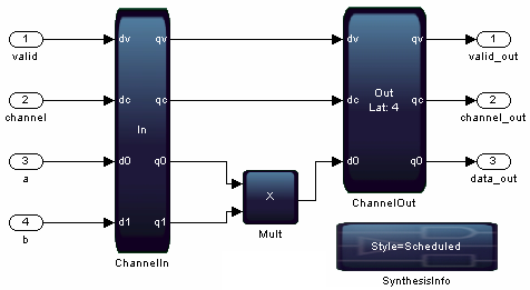
To reach the desired fMAX, DSP Builder then inserts four pipelining stages in the multiplier, and balances these with four registers on the channel and valid paths. To correct the simulation design example to match hardware, the ChannelOut block delays the outputs by four cycles in simulation and displays Lat: 4 on the block. Thus, if you compare the output of the multiplier simulation with the hardware it is now four cycles early in simulation; but if you compare the primitive subsystem outputs with hardware they match, because the ChannelOut block provides the simulation correction for the automatically inserted pipelining.
If you want a consistent 10 cycles of delay across the valid, channel and datapath, you may need latency constraints.
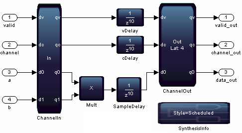
This example has a consistent line of SampleDelay blocks inserted across the design. However, the algorithm does not use these delays. DSP Builder recognizes that designs do not require them and optimizes them away, leaving only the delay that designs require. In this case, each block requires a delay of four, to balance the four delay stages to pipeline the multiplier sufficiently to reach the target fMAX. The delay of 10 in simulation remains from the non-direct-feed-through SampleDelay blocks. In such cases, you receive the following warning on the MATLAB command line:
DSP Builder optimizes away some user inserted SampleDelays. The latency on the valid path across primitive subsystem design name in hardware is 4, which may differ from the simulation model. If you need to preserve extra SampleDelay blocks in this case, use the Constraint Latency option on the SynthesisInfo block.