DSP Builder for Intel® FPGAs (Advanced Blockset): Handbook
A newer version of this document is available. Customers should click here to go to the newest version.
9.6.6. Control Units Delays
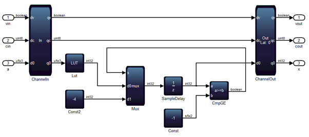
DSP Builder relocates the sample delay, to save registers, to the Boolean signal that drives the s-input of the 2-to-1 Mux block. You may see a mismatch in the first cycle and beyond, depending on the contents of the LUT.
When you design a control unit as an FSM, the locations of SampleDelay blocks specify where DSP Builder expects zero values during the first cycle. In Figure 86, DSP Builder expects the first sample that the a-input receives of the CmpGE block to be zero. Therefore, the first output value of that compare block is high. Delay redistribution changes this initialization. You cannot rely on the reset state of that block, especially if you embed the Primitive subsystem within a larger design. Other subsystems may drive the feedback loop whose pipeline depth adapts to fMAX. The first valid sample may only enter this subsystem after some arbitrary number of cycles that you cannot predetermine. To avoid this problem, always ensure you anchor the SampleDelay blocks to the valid signal so that the control unit enters a well-defined state when valid-in first goes high.
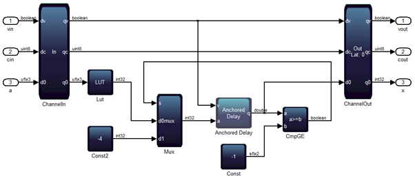
To make a control unit design resistant to automated delay redistribution and to solve most hardware FSM designs that fail to match simulation, replace every SampleDelay block with the Anchored Delay block from the Control folder in the Additional libraries. When the valid-in first goes high, the Anchored Delay block outputs one (or more) zeros, otherwise it behaves just like an ordinary SampleDelay block.
Synthesizing the example design (fMAX = 250MHz) on Arria V (speedgrade 4), shows that DSP Builder is still redistributing the delays contained inside of the Anchored Delay block to minimize register utilization. DSP Builder still inserts a register initialized to zero before the s-input of the 2-to-1 Mux block. However, the hardware continues to match Simulink simulation because of the anchoring. If you place highly pipelined subsystems upstream so that the control unit doesn't enter its first state until several cycles after device initialization, the FSM still provides correct outputs. Synchronization is maintained because DSP Builder inserts balancing delays on the valid-in wire that drives the Anchored Delay and forces the control unit to enter its initial state the correct number of cycles later.
Control units that use this design methodology are also robust to optimizations that alter the latency of components. For example, when a LUT block grows sufficiently large, DSP Builder synthesizes a DualMem block in its place that has a latency of at least one cycle. Automated delay balancing inserts a sufficient number of one bit wide delays on the valid signal control path inside every Anchored Delay. Hence, even if the CmpGE block is registered, its reset state has no influence on the initial state of the control unit when the valid-in first goes high.
Each Anchored Delay introduces a 2-to-1 Mux block in the control path. When targeting a high fMAX (or slow device) tight feedback loops may fail to schedule or meet timing. Using Anchored Delay blocks in place of SampleDelay blocks may also use more registers and can also contribute to routing congestion.