DSP Builder for Intel® FPGAs (Advanced Blockset): Handbook
A newer version of this document is available. Customers should click here to go to the newest version.
14.6.6. Finite State Machine
FSM Specification Language
The FSM specification language supports the following features:
- Boolean expressions to form state transition diagrams
- Nested, dependent, loops which allow you to express, for example, rectangular and triangular iteration counters
- Automatic dead cycle hiding for nested ForLoop control logic
The configuration text file specifies the control logic that the Finite State Machine block generates.
The file has two sections:
- Options that are optional settings to override certain defaults such as the name of the XML file and external port names
- Netlist components that define the ForLoop blocks and state transitions, and how they fit together (i.e. nesting or sequencing structure) that defines the behavior of the state machine
The keyword netlist separates these two sections:
option settings ...
netlist...
netlist components ...
Options
| Option | Description |
|---|---|
| require version <version> | Specify the version of the Finite State Machine that you require. The version is in the form N.NN (eg: require version 23.3). You must always specify this line. |
| inputs <port-name> | Specify one or more Boolean input ports that DSP Builder uses in conditional expressions for state transitions. |
| enable <port-name> | Add an optional enable with the specified port name. Default is to tie enable to VCC. |
| start <port-name> | Specify a different name for the go port. A one-cycle pulse on this port starts the Finite State Machine block. |
| finish <port-name> | Add a finish port with the name as specified. The port emits a one-cycle pulse from this port when the Finite State Machine completes. This port allows two or more Finite State Machine blocks to daisy chain, or to nest a Finite State Machine in a ForLoop block. |
# this is a comment
require version 23.3
inputs d0 d1
enable en
start begin
finish done
netlist
    ...
Netlist Components
Netlist components can be:
- State transitions
- ForLoop blocks
State Transitions
To define state transitions:
transitions <name> : <port-name> ...
 ... state transitions
end
You specify state transitions by the following inputs:
- state <current-state>
- if (<condition>) <next-state> <output-value> ...
- Each state definition can be followed by one or more if transition statements. The last transition of a state definition can be a catch-all default transition:
- default <next-state> <output-value> ...
transitions Sticky : q r
    state Start
        if (a) Next 1 0
        default Start 1 1
    state Next
        if (~a) Start 0 1
end
If you omit default, the Finite State Machine assumes an implicit catch all default transition where the next-state is the same as the current state and all output values are 0.
The Finite State Machine normally generates a Mealy Machine type of state transition control unit. To generate a Moore Machine, add the moore option to the transitions specification, and use output to define the output signal values for each state. For example:
transitions Sticky : q r
    moore
    state Start
        output 0 1
        if (a) Next
    state Next
        output 1 0
        if (~a) Start
end
You can specify a finish port for a state transition style Finite State Machine that produces a pulse for one cycle when the Finite State Machine returns back to its initial state on completion. This behavior corresponds to passing on the token to the next Finite State Machine component in the sequence. Receiving a go signal pulse (i.e. a token) activates in turn each Finite State Machine component in the sequence.
transitions Wait : q r
finish waitDone
 ... state transitions
end
State Transition Diagram
The Finite State Machine block can implement a Mealy Machine or Moore Machine state diagram.
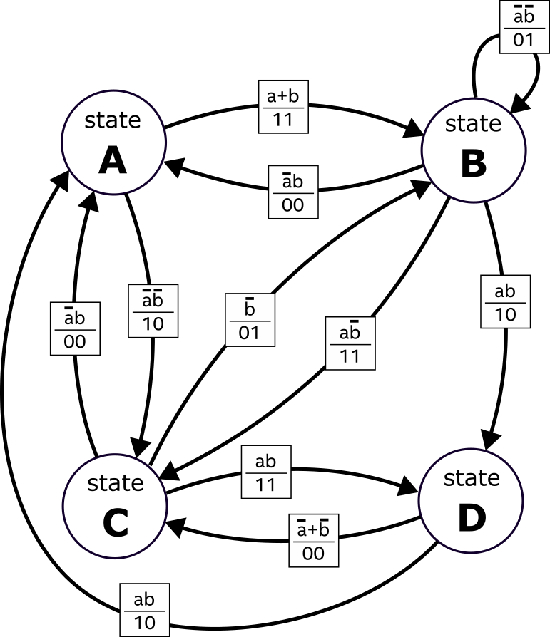
This example state diagram has two inputs: a, b; and two outputs: q1, q0. Negations are (~x), conjunctions (x & y), and disjunctions (x | y). The output values for ports, q1 and q0, are at the end of the if statements
# Mealy Machine
require version 23.3
inputs a b
netlist
transitions Mealy : q1 q0
    state A
        if (a | b) B 1 1
        if (~a & ~b) C 1 0
    state B
        if (~a & b) A 0 0
        if (~a & ~b) B 0 1
        if (a & ~b) C 1 1
        if (a & b) D 1 0
    state C
        if (~a & b) A 0 0
        if (~b) B 0 1
        if (a & b) D 1 1
    state D
        if (a & b) A 1 0
        if (~b | ~a) C 0 0
end
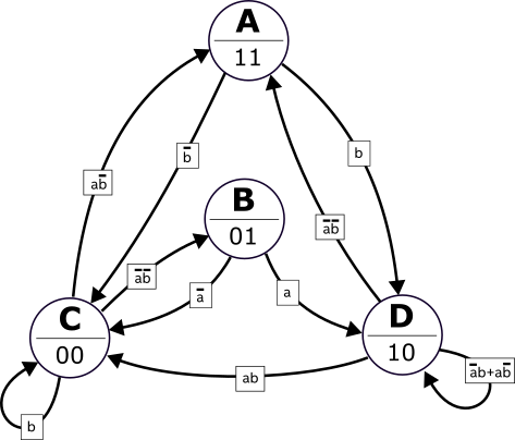
The keyword output indicates the output values for ports, q1 and q0, for each defined state. The condition for the D?D transition, ((~a & b) | (a & ~b)), is equivalent to the exclusive OR, (a ^ b).
# Moore Machine
require version 23.3
inputs a b
netlist
transitions Moore : q1 q0
    moore
    state A
        output 1 1
        if (~b) C
        if (b) D
    state B
        output 0 1
        if (~a) C
        if (a) D
    state C
        output 0 0
        if (a & ~b) A
        if (~a & ~b) B
        if (b) C
    state D
        output 1 0
        if (~a & ~b) A
        if (a & b) C
        if (a ^ b) D
end
ForLoop Blocks
Instantiates a ForLoop block <name> and inequality operator set to <, <=, >, or >=. The values that you specify for <init>, <step>, and <limit> drive the input ports of the ForLoop block.
for <name> <init> <inequality-op> <limit> step <step>: <port-name> ...
 ... nested components
end
for x 0 < 8
end
The port-names are optional. If specified, they must correspond to the names of ForLoop output ports:
| Name | Output Port |
|---|---|
| bs | Body Start |
| ld | Loop Done |
| el | Empty Loop |
| fl | First Loop |
| ll | Last Loop |
| v | Valid |
| c | Counter |
for x 8 >= 0 step -1 : ld v c
end
Nested ForLoops
You can nest ForLoop blocks.
for x 8 >= 3 step -1
    for y 0 < x

    end
end
for row 0 < 8 : c
    for col 0 < 8 : c v

    end
end
for row 1 < 8 : c
    for col 0 < row : c v

    end
end
- The ForLoop limits and step size can only be a constant integer or the counter value of an enclosing ForLoop block. DSP Builder does not support arbitrary mathematical expressions (e.g. 2*row+1).
- The Finite State Machine block does not support vector ForLoop blocks
You can also nest state transitions inside ForLoop definitions:
inputs y
netlist
for x 0 < 8
    transitions Simple : q
        state Start
            if (y) Next 1
        state Next
            if (~y) Start 0
    end
end
Unlike when nesting Forloop blocks, state transitions cannot make use of the counter value of the enclosing ForLoop.
To join ForLoop and state transitions in a sequence, declare them one after the other in the configuration file
inputs y
netlist
for x 0 < 8
end
transitions Simple : q
    state Start
        if (y) Next 1
    state Next
        if (~y) Start 0
end
Strategies for Hiding Dead Cycles
DSP Builder holds the valid output (v) of the ForLoop block at zero for at least one cycle whenever the counter is reset to the starting value after it reaches the end limit value. This dead cycle can reduce throughput for designs that use nested ForLoop blocks.
When the outer For-Loop block reinitialises the inner nested ForLoop block, DSP Builder holds the valid out low for one cycle. You can hide this cycle by overlapping it with a valid iteration. You enable the different dead cycle strategies by using the option, dead cycle <strategy>
| Strategy | Description |
|---|---|
| endearly | ForLoop exits one cycle early |
| shiftrange | Outer ForLoop iterations overlaps with first iteration of inner ForLoop. This strategy is limited to ForLoop blocks with constant limits and does not work when the inner ForLoop uses the counter of the outer ForLoop. Supports deeper nesting. |
| oneahead | Outer ForLoop iterations overlaps with first iteration of inner ForLoop. This strategy also works when the inner ForLoop uses the counter of the outer ForLoop. Does not support deeper nesting. |
for row 0 < 8 : c

    deadcycle endearly

    for col 0 < 8 : c v

    end

end
The deadcycle endearly strategy is a simple transformation of the netlist that reduces the number of iterations of the innermost loop by one. The example is functionally equivalent to:
for row 0 < 8 : c

    for col 0 < 7 : c v

    end

end
This strategy only makes sense if the innermost ForLoop body is empty or has zero latency. The one cycle in the outer loop iteration effectively overlaps the final iteration of the inner loop. The control signals also reflect the shortened iteration space such that the last loop and loop done signals go high one cycle earlier. You need to compensate for this behavior in your design.
for x 0 < 4

    deadcycle shiftrange


    for y 8 >= 1 step -1

        deadcycle shiftrange


        for z 0 < y : v c

        end

    end

end
The deadcycle shiftrange strategy overlaps each iteration of the outer ForLoop block with the first iteration of the inner ForLoop block. However, in triangular nested iteration, the inner ForLoop needs to access the outer ForLoop block's counter value before it completes its own iteration cycle. To resolve this dependency, the outer ForLoop iterates over the range from (init+step) to (limit+step), i.e. its range shifts forward by one iteration step. This transformation only applies if the outer ForLoop block's parameters are all constants. The following construction does not work:
for x 0 < 4

    for y 8 >= x step -1
        deadcycle shiftrange

        for z 1 < 5
The middle ForLoop block's limit depends on the outer ForLoop block's counter. It is not trivial to shift the range of the y-ForLoop without affecting other ForLoop blocks.
The Finite State Machine block constructs a chain of nested ForLoop blocks as specified by the .fsm configuration file.
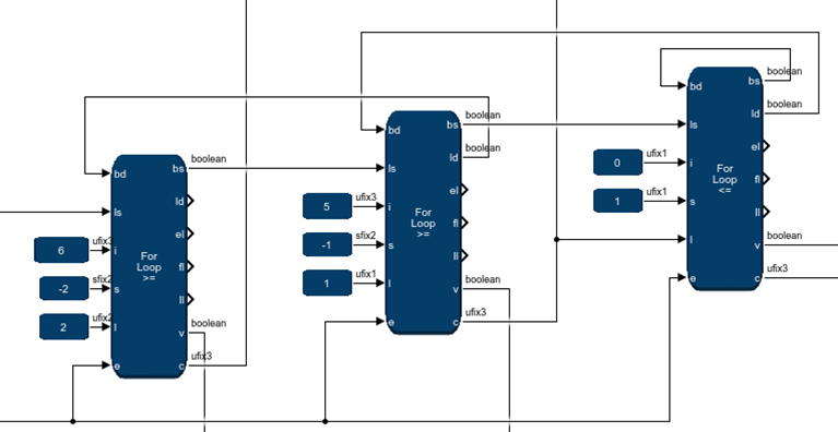
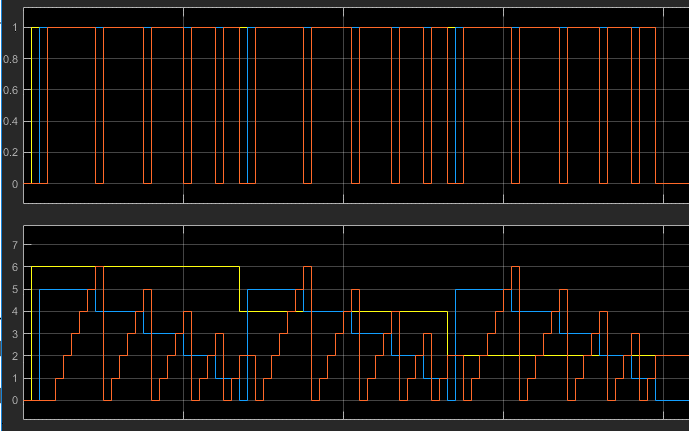

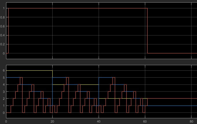
for x 5 > 1 step -1 : c

    for y 8 >= x step -1

        deadcycle oneahead

        for z 0 <= y : v c


        end

    end

end
The deadcycle_oneahead strategy is similar to the shiftrange strategy but the FSM does not require the inner ForLoop block's parameters to be constants. In the example, the middle ForLoop block's limit is the outer ForLoop block's counter. The netlist transformation uses more elaborate control logic that pre-advances the outer ForLoop by one iteration before initializing the inner ForLoop. This approach doesn't work for deeper nesting structures such as:
for x 5 > 1 step -1 : c

    deadcycle oneahead

    for y 8 >= 1 step -1

        deadcycle oneahead

        for z 0 < y : v c
Although the Finite State Machine hides the dead-cycle in the outer ForLoop, the Finite State Machine inserts an extra cycle to pre-advance the middle ForLoop when applying its dead-cycle hiding strategy.
You can mix and match the different dead-cycle hiding strategies
Section Content
Adding a Finite State Machine Block to your DSP Builder Design
Modifying the Finite State Machine Block Specification File
Implement Token Passing with the Finite State Machine
Implementing a One Shot Counter with the Finite State Machine
Specifying ForLoop Control Units
Creating the Finite State Machine Configuration File
Upgrading Finite State Machine Blocks from v23.2 and Earlier