Intel Agilex® 7 M-Series FPGA Network-on-Chip (NoC) User Guide
A newer version of this document is available. Customers should click here to go to the newest version.
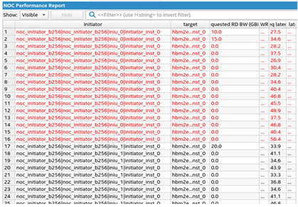
3.6.4. NoC Performance Reports in Interface Planner
At any point during NoC initiator placement, you can interactively generate a NoC Performance Report in Interface Planner. The NoC Performance Report generation performs a static analysis of the NoC initiator and target locations to evaluate whether the placement allows your design to meet the bandwidth requirements and transaction sizes that you specify in the NoC Assignment Editor.
To access the NoC Performance Report in Interface Planner, click the Reports tab, and then double-click Report NoC Performance in the Tasks pane.
The NoC Performance Report reports performance data for each initiator to target connection. You can achieve lower minimum structural latency by placing the NoC initiators and targets closer together.
| NoC Performance Report Column | Description |
|---|---|
| Requested RD BW | The requested read bandwidth in GB per second. This value is the same as the value that you specify in the NoC Assignment Editor, as Step 3: Make Attribute Assignments in the NoC Assignment Editor describes. |
| Requested WR BW | The requested write bandwidth in GB per second. This value is the same as the value that you specify in the NoC Assignment Editor. |
| Initiator placement | The placement location of the initiator element. |
| Target placement | The placement location of the target element. |
| Message | A message indicating whether you can achieve the requested bandwidth, or whether the connection is congested; and information about the cause of the congestion. The cause of congestion is an indication of where the congestion occurs, and which other connections contribute to that congestion. |
One possible reason that the Message reports that the current placement cannot meet the requested bandwidth is because of over-saturation of an initiator or a target. For example, if the sum of all bandwidth requirements through a particular initiator is greater than the bandwidth that the initiator can support, based on the data width and operating frequency of its fabric facing AXI4 interface. To avoid this problem, either reduce bandwidth requirements or increase bandwidth capability.
Another possible reason that the current placement cannot meet the requested bandwidth is over-saturation of the horizontal bandwidth available in the NoC. This condition is the result of multiple initiator to target connections requesting bandwidth over the same sections of the horizontal links.
Further congestion can arise for connections that overlap connections that are already congested for any of the above reasons.