Intel Agilex® 7 M-Series FPGA Network-on-Chip (NoC) User Guide
A newer version of this document is available. Customers should click here to go to the newest version.
3.6. Making NoC Physical Assignments Using Interface Planner
After design synthesis, you can use the Intel® Quartus® Prime Interface Planner to help you to make physical assignments to define a legal device floorplan.
Interface Planner allows you to assign physical locations for the periphery elements in your design, such as external memory interfaces or other general purpose I/O. You can also use Interface Planner to assign physical locations for NoC initiators, PLLs, and SSMs. For step-by-step instructions on using Interface Planner, refer to Using Interface Planner.
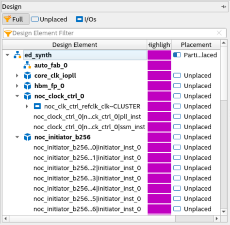
Interface Planner displays your project's logical hierarchy, post-synthesis design elements, and Fitter-created design elements, alongside a floorplan view of target device locations. The GUI supports a variety of methods for placing design elements in the floorplan. As you place elements in the floorplan, the Fitter verifies legality in real time to ensure accurate correlation with the final implementation.
You can use Interface Planner to assign physical locations for NoC initiators, targets (as part of the HBM2e or external memory interfaces), PLLs, and SSMs. If you do not make physical assignments for NoC elements, the Fitter places NoC elements automatically during compilation. However, the Fitter automatic placement does not optimize for bandwidth utilization.
It is best to place NoC initiators that communicate with AXI4 Lite targets close to the NoC SSM. This placement reduces AXI4 Lite access latency and separates AXI4 Lite and memory traffic on the hard memory NoC.
You use the floorplan view in Interface Planner to place hard memory NoC and periphery elements. There are three floorplan views available:
- NoC View—shows a filtered view of NoC initiators and targets.
- Chip View—shows the placeable locations for hard memory NoC elements, including NoC initiators, targets, PLLs, and SSMs.
- Package View—NoC elements are not visible in the Package View.
In the Chip View, the available NoC initiator and target locations appear as rows of small boxes across the top and bottom edges of the device, between the FPGA fabric and the periphery I/O structures. Placing your cursor over locations displays a tooltip indicating whether the location supports only an initiator, only a target, or both an initiator and a target.
The available NoC PLL and NoC SSM locations appear as smaller boxes at the end of the row of initiators and targets. The PLL and SSM locations appear at the left end of the rows (if using the Chip Top view), or at the right end of the rows (if using the Chip Bottom view). The HPS appears at the top right (if using the Chip Top view) or at the top left (if using the Chip Bottom view).
Figure 46. Interface Planner Chip View, Closeup of NoC Features shows an example of the Interface Planner Chip View showing the top left corner of the die as viewed from the top. The two smaller pink boxes at the top left corner of the fabric are the locations of the NoC PLL and the NoC SSM.
In the NoC View, only the NoC initiators and targets are visible as larger rectangles. The targets and initiators for both high-speed NoC along the top edge of the die, and the high-speed NoC along the bottom edge of the die, are visible. The NoC View splits the initiators and targets that may share the same location in the Chip View.
The outer-top and outer-bottom rows are the targets for the top-edge NoC and bottom-edge NoC, respectively. Similarly, the inner-top and inner-bottom rows are the initiators for the top-edge NoC and bottom-edge NoC, respectively. As with the Chip View, if you place your cursor over one of these locations, a tooltip reports if that location supports a target or an initiator.
Figure 47. NoC View Showing Targets and Initiators is an example of the Interface Planner NoC View showing the targets and initiators for both the top-edge NoC and the bottom-edge NoC. The row of initiators along the top edge shows 21 rectangles. 20 of these rectangles are for fabric-facing initiators. The last rectangle contains the two HPS-facing initiators.