Intel® Quartus® Prime Standard Edition User Guide: Debug Tools
2.10. ADC Toolkit
Prerequisites for Using the ADC Toolkit
- Altera Modular ADC IP core
- External Reference Voltage if you select External in the Altera Modular ADC IP parameters
- Reference signal
The ADC Toolkit needs a sine wave signal to be fed to the analog inputs. You need the capability to precisely set the level and frequency of the reference signal. A high-precision sine wave is needed for accurate test results; however, there are useful things that can be read in Scope mode with any input signal.
To achieve the best testing results, ensure that the reference signal has less distortion than the device ADC is able to resolve. Otherwise, you are adding distortions from the source into the resulting ADC distortion measurements. The limiting factor is based on hardware precision.
Configuring the Altera Modular ADC IP Core
The Altera Modular ADC IP core needs to be included in the design. You can instantiate this IP core from the IP Catalog. When you configure this IP core in the Parameter Editor, you need to enable the Debug Path option located under Core Configuration.
There are two limitations in the Intel® Quartus® Prime software v14.1 for the Altera Modular ADC IP core. The ADC Toolkit does not support the ADC control core only option under Core Configuration. You must select a core variant that uses the standard sequencer in order for the Altera Modular ADC IP core to work with ADC Toolkit. Also, if an Avalon® Master is not connected to the sequencer, you must manually start the sequencer before the ADC Toolkit.

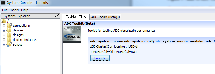
Starting the ADC Toolkit
You can launch the ADC Toolkit from System Console. Before starting the ADC toolkit, you need to verify that the board is programmed. You can then load the .sof by clicking File > Load Design. If System Console was started with an active project, the design is auto-loaded when you start System Console.
There are two methods to start the ADC Toolkit. Both methods require you to have a Intel® MAX® 10 device connected, programmed with a project, and linked to this project. However, the Launch command only shows up if these requirements are met. You can always start the ADC Toolkit from the Tools menu, but a successful connection still depends on meeting the above requirements.
- Click Tools > ADC Toolkit
- Alternatively, click Launch from the Toolkits tab. The path for the device is displayed above the Launch button.
Upon starting the ADC Toolkit, an identifier path on the ADC Toolkit tab shows you which ADC on the device is being used for this instance of the ADC Toolkit.
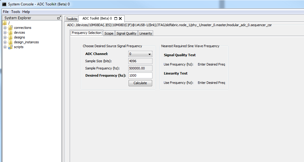
ADC Toolkit Flow
The ADC Toolkit GUI consists of four panels: Frequency Selection, Scope, Signal Quality, and Linearity.
- Use the Frequency Selection panel to calculate the required sine wave frequency for proper signal quality testing. The ADC Toolkit provides the nearest ideal frequency based on the desired reference signal frequency.
- Use the Scope panel to tune the signal generator or inspect input signal characteristics.
- Use the Signal Quality panel to test the performance of the ADC using industry standard metrics.
- Use the Linearity panel to test the linearity performance of the ADC and display differential and integral non-linearity results.