Intel® Quartus® Prime Standard Edition User Guide: Debug Tools
ID
683552
Date
9/24/2018
Public
1. System Debugging Tools Overview
2. Analyzing and Debugging Designs with System Console
3. Debugging Transceiver Links
4. Quick Design Debugging Using Signal Probe
5. Design Debugging with the Signal Tap Logic Analyzer
6. In-System Debugging Using External Logic Analyzers
7. In-System Modification of Memory and Constants
8. Design Debugging Using In-System Sources and Probes
A. Intel® Quartus® Prime Standard Edition User Guides
2.1. Introduction to System Console
2.2. System Console Debugging Flow
2.3. IP Cores that Interact with System Console
2.4. Starting System Console
2.5. System Console GUI
2.6. System Console Commands
2.7. Running System Console in Command-Line Mode
2.8. System Console Services
2.9. Working with Toolkits
2.10. ADC Toolkit
2.11. System Console Examples and Tutorials
2.12. On-Board Intel® FPGA Download Cable II Support
2.13. MATLAB* and Simulink* in a System Verification Flow
2.14. Deprecated Commands
2.15. Analyzing and Debugging Designs with the System Console Revision History
2.9.6.4.1. toolkit_register
2.9.6.4.2. toolkit_open
2.9.6.4.3. get_quartus_ini
2.9.6.4.4. toolkit_get_context
2.9.6.4.5. toolkit_get_types
2.9.6.4.6. toolkit_get_properties
2.9.6.4.7. toolkit_add
2.9.6.4.8. toolkit_get_property
2.9.6.4.9. toolkit_set_property
2.9.6.4.10. toolkit_remove
2.9.6.4.11. toolkit_get_widget_dimensions
2.9.6.5.1. Widget Types and Properties
2.9.6.5.2. barChart Properties
2.9.6.5.3. button Properties
2.9.6.5.4. checkBox Properties
2.9.6.5.5. comboBox Properties
2.9.6.5.6. dial Properties
2.9.6.5.7. fileChooserButton Properties
2.9.6.5.8. group Properties
2.9.6.5.9. label Properties
2.9.6.5.10. led Properties
2.9.6.5.11. lineChart Properties
2.9.6.5.12. list Properties
2.9.6.5.13. pieChart Properties
2.9.6.5.14. table Properties
2.9.6.5.15. text Properties
2.9.6.5.16. textField Properties
2.9.6.5.17. timeChart Properties
2.9.6.5.18. xyChart Properties
3.1. Channel Manager
3.2. Transceiver Debugging Flow Walkthrough
3.3. Modifying the Design to Enable Transceiver Debug
3.4. Programming the Design into an Intel FPGA
3.5. Loading the Design in the Transceiver Toolkit
3.6. Linking Hardware Resources
3.7. Identifying Transceiver Channels
3.8. Creating Transceiver Links
3.9. Running Link Tests
3.10. Controlling PMA Analog Settings
3.11. User Interface Settings Reference
3.12. Troubleshooting Common Errors
3.13. Scripting API Reference
3.14. Debugging Transceiver Links Revision History
3.3.2.1. Bit Error Rate Test Configuration ( Stratix® V)
3.3.2.2. PRBS Signal Eye Test Configuration ( Stratix® V)
3.3.2.3. Custom Traffic Signal Eye Test Configuration ( Stratix® V)
3.3.2.4. Link Optimization Test Configuration ( Stratix® V)
3.3.2.5. PMA Analog Setting Control Configuration ( Stratix® V)
4.1.1. Perform a Full Compilation
4.1.2. Reserve Signal Probe Pins
4.1.3. Assign Signal Probe Sources
4.1.4. Add Registers Between Pipeline Paths and Signal Probe Pins
4.1.5. Perform a Signal Probe Compilation
4.1.6. Analyze the Results of a Signal Probe Compilation
4.1.7. What a Signal Probe Compilation Does
4.1.8. Understanding the Results of a Signal Probe Compilation
4.2.1. Making a Signal Probe Pin
4.2.2. Deleting a Signal Probe Pin
4.2.3. Enabling a Signal Probe Pin
4.2.4. Disabling a Signal Probe Pin
4.2.5. Performing a Signal Probe Compilation
4.2.6. Reserving Signal Probe Pins
4.2.7. Adding Signal Probe Sources
4.2.8. Assigning I/O Standards
4.2.9. Adding Registers for Pipelining
4.2.10. Running Signal Probe Immediately After a Full Compilation
4.2.11. Running Signal Probe Manually
4.2.12. Enabling or Disabling All Signal Probe Routing
4.2.13. Allowing Signal Probe to Modify Fitting Results
5.1. The Signal Tap Logic Analyzer
5.2. Signal Tap Logic Analyzer Task Flow Overview
5.3. Configuring the Signal Tap Logic Analyzer
5.4. Defining Triggers
5.5. Compiling the Design
5.6. Program the Target Device or Devices
5.7. Running the Signal Tap Logic Analyzer
5.8. View, Analyze, and Use Captured Data
5.9. Other Features
5.10. Design Example: Using Signal Tap Logic Analyzers
5.11. Custom Triggering Flow Application Examples
5.12. Signal Tap Scripting Support
5.13. Design Debugging with the Signal Tap Logic Analyzer Revision History
5.3.1. Assigning an Acquisition Clock
5.3.2. Adding Signals to the Signal Tap File
5.3.3. Adding Signals with a Plug-In
5.3.4. Adding Finite State Machine State Encoding Registers
5.3.5. Specifying Sample Depth
5.3.6. Capture Data to a Specific RAM Type
5.3.7. Select the Buffer Acquisition Mode
5.3.8. Specifying Pipeline Settings
5.3.9. Filtering Relevant Samples
5.3.10. Manage Multiple Signal Tap Files and Configurations
5.5.1. Faster Compilations with Intel® Quartus® Prime Incremental Compilation
5.5.2. Prevent Changes Requiring Recompilation
5.5.3. Verify Whether You Need to Recompile Your Project
5.5.4. Incremental Route with Rapid Recompile
5.5.5. Timing Preservation with the Signal Tap Logic Analyzer
5.5.6. Performance and Resource Considerations
5.8.1. Capturing Data Using Segmented Buffers
5.8.2. Differences in Pre-Fill Write Behavior Between Different Acquisition Modes
5.8.3. Creating Mnemonics for Bit Patterns
5.8.4. Automatic Mnemonics with a Plug-In
5.8.5. Locating a Node in the Design
5.8.6. Saving Captured Data
5.8.7. Exporting Captured Data to Other File Formats
5.8.8. Creating a Signal Tap List File
5.9.1. Creating Signal Tap File from Design Instances
5.9.2. Using the Signal Tap MATLAB* MEX Function to Capture Data
5.9.3. Using Signal Tap in a Lab Environment
5.9.4. Remote Debugging Using the Signal Tap Logic Analyzer
5.9.5. Using the Signal Tap Logic Analyzer in Devices with Configuration Bitstream Security
5.9.6. Monitor FPGA Resources Used by the Signal Tap Logic Analyzer
6.1. About the Intel® Quartus® Prime Logic Analyzer Interface
6.2. Choosing a Logic Analyzer
6.3. Flow for Using the LAI
6.4. Controlling the Active Bank During Runtime
6.5. Using the LAI with Incremental Compilation
6.6. LAI Core Parameters
6.7. In-System Debugging Using External Logic Analyzers Revision History
7.2.1. Instance Manager
7.2.2. Editing Data Displayed in the Hex Editor Pane
7.2.3. Importing and Exporting Memory Files
7.2.4. Scripting Support
7.2.5. Programming the Device with the In-System Memory Content Editor
7.2.6. Example: Using the In-System Memory Content Editor with the Signal Tap Logic Analyzer
8.1. Hardware and Software Requirements
8.2. Design Flow Using the In-System Sources and Probes Editor
8.3. Compiling the Design
8.4. Running the In-System Sources and Probes Editor
8.5. Tcl interface for the In-System Sources and Probes Editor
8.6. Design Example: Dynamic PLL Reconfiguration
8.7. Design Debugging Using In-System Sources and Probes Revision History
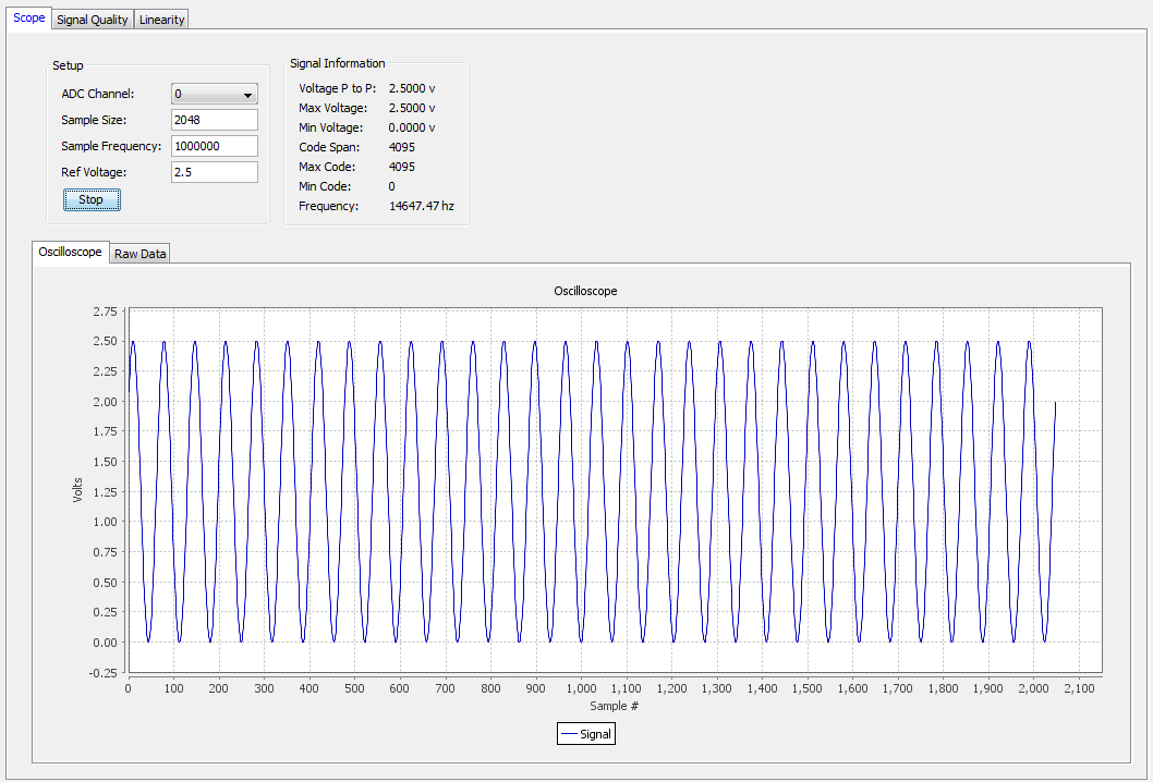
2.10.3. Tuning the Signal Generator
The Scope panel allows you to tune the signal generator in order to achieve the best possible performance from the ADC.
Figure 14. Scope Mode Panel
To tune the signal generator:
- On ADC Channel, select the ADC channel that you plan to test.
- Enter the reference Sample Frequency (unless the tool can extract this value from the IP).
- Enter the Ref Voltage (unless the tool can extract this value from the IP).
- Click Run.
The tool repeatedly captures a buffer worth of data and displays the data as a waveform, besides additional information under Signal Information.
- Tune the signal generator to use the maximum dynamic range of the ADC without clipping.
Note: Avoid hitting 0 or 4095 because of signal clipping.
- Ensure that the sine wave under Oscilloscope shows evenly balanced top and bottom peaks. This indicates optimum value.
- For Intel® MAX® 10 devices, you want to get as close to Min Code = 0 and Max Code = 4095 without actually hitting those values.
- To observe coherent sampling in the test window, you must set the frequency precisely to the value needed for testing, Before moving forward, follow the suggested value for signal quality testing or linearity testing that appears next to the detected frequency.
- From the Raw Data tab, export the data as a .csv file.
Related Information