Video and Vision Processing Suite Intel® FPGA IP User Guide
A newer version of this document is available. Customers should click here to go to the newest version.
26.3. Scaler IP Functional Description
Nearest neighbor
The nearest neighbor algorithm requires a line buffer with storage for a single line of the input field to allow for this line to repeat multiple times at the output during upscales. Because nearest neighbor scaling does not involve any interpolation or filtering, the resulting image can have a blocky appearance.
Bilinear
Bilinear scaling offers improved quality compared to nearest neighbor by interpolating between neighboring pixels to remove the blocky look of nearest neighbor scaling. Bilinear scaling is better suited to upscaling (increasing image size) than downscaling (reducing image size). The cut-off frequency of the basic bilinear filter is generally too high to remove all the aliasing artifacts that downscaling can introduce. However, even for upscales the results can look somewhat blurred, with the edges in the image softened.
The bilinear algorithm selects the same input pixel to create each output pixel as the nearest neighbor algorithm. It builds a 2x2 pixel window around the target input pixel, with the target pixel in the top left corner of the window. The floor function calculates the input pixel position (the values of x and y) to give integer indices, as pixels only exist at integer locations. But the integer indices have some error compared to the ideal location that preserves all the fractional position information. For example, if the ideal value before applying the floor function is 1.5, the integer value after applying the floor function is 1, and the error is 0.5. The bilinear algorithm uses the horizontal and vertical position error values, err h and err v respectively, to create coefficients that, when applied to the 2x2 pixel window created around the integer pixel location, produce a resulting pixel that is effectively located at the desired fractional position. The equations show how the values of the coefficients are created and applied to the input window of pixels to create the output pixel.
To calculate the values of err h and err v with exact precision for all possible scaling ratios requires an infinite number of fractional bits in the hardware implementing the mathematics. You must specify via parameters how many fraction bits you want to include for the calculations in the horizontal and vertical directions, frac h and frac v respectively. The IP takes the value for frac h from the Horizontal coefficient fraction bits parameter, and the value for frac v from the Vertical coefficient fraction bits parameter. With the desired level of precision set, the equation shows the values of and
To create the 2x2 pixel window required for the bilinear filter, the bilinear algorithm requires a line buffer with storage for two lines of input video.
Polyphase
The polyphase algorithm requires the most resources, but it produces the highest quality results. It uses interpolation filters that are larger than the 2x2 tap filter used for bilinear scaling. Depending on the coefficients you select, these filters can provide improved frequency response, resulting in less blurring on the edges during upscales, and less aliasing artifacts during downscales. The increased size of the filters requires an increase in the number of input video lines that must be stored to create the vertical window, and increased DSP block (multiplier) usage to implement the filter mathematics.
The polyphase algorithm uses the same initial integer pixel position as nearest neighbor scaling and calculates positional error values in the same way as the bilinear algorithm. However, instead of using these error values directly to calculate the filter coefficients, the polyphase algorithm uses the error values as addresses into horizontal and vertical filter coefficients memories. Each address in the coefficient memory is referred to as a phase (for reasons that are explained in the coefficient selection section) and you define the number of horizontal and vertical phases, num_phase h and num_phase v respectively, via parameters. The Number of horizontal phases parameter sets the value for num_phase h and the Number of vertical phases parameter sets the value for num_phase v . The equation shows the horizontal phase, phase h , and the vertical phase, phase v , for each output pixel:
You define the number of taps used in the horizontal and vertical scaling filters (num_taps h and num_taps v respectively). The number of taps can be any value between 4 and 64. A higher number of taps can allow for a more precise filter transfer function but comes at the cost of extra DSP block utilization and, in the case of the vertical filter, increased block memory utilization in the line buffer required to create the vertical sample window. Each vertical or horizontal phase in the coefficient memory contains one coefficient for each tap of the vertical or horizontal filter.
The scaler implements the vertical scaling function first (if selected), followed by the horizontal scaling function (if selected). The result of the vertical scaling is an intermediate image with the desired output height but retaining the original input width. If inter[x,j] as the pixel value in the intermediate image at horizontal position x and vertical position j, and coeff f v [n] as the vertical scaling filter coefficient for tap N (selected from phase v ), the equation shows how the IP calculates the intermediate image. The filter taps are indexed with 0 the ‘oldest’ data (closest to the top edge of the image) and num_taps v - 1 the newest data (closest to the bottom edge of the image).
If coeff f h [n] is the horizontal scaling filter coefficient for tap N (selected from phase v ), the equation shows how the IP calculates the final output image from the intermediate image. The filter taps are again indexed with 0 the oldest data (closest to the left edge of the image) and num_taps h - 1 the newest data (closest to the right edge of the image)
Coefficient selection
If you select polyphase scaling, the coefficients that the scaling filters use are read from a memory. You must define the contents of this memory. You are free to write whatever values you want to the coefficient memory, and if you already have well defined coefficient sets that you use, the flexibility in the scaler to select the desired number of filter taps and phases should allow you to continue with these. If you are new to scaling, read the following guidance on coefficient selection.
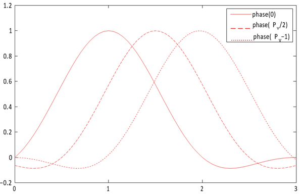
Generally, the set of coefficients that the IP writes to filter phase 0 yield a low-pass filter, with most weight in generating the output pixel value given to the pixel value in tap . The function is centered at tap . The coefficients the IP writes to the other phases are then just phase shifted versions of this function (hence the name phase for each coefficient address), with the function centered at a point that is shifted by 1/ num_of_pixels of a pixel with every subsequent phase.
The Lanczos function is a common function that defines scaling coefficients. The Lanczos function is a base sinc function, with the primary lobe of a sinc function used as a window function to preserve a given number of lobes of the base sinc. The number of lobes is generally appended to Lanczos when referring to a specific variant of the function, so a Lanczos function where two lobes are preserved is referred to as Lanczos2. In the case where N lobes are preserved, the LanczosN function is defined as:
When using LanczosN coefficients, Intel recommends configuring the scaler filters with the following numbers of taps for the upscale and downscale cases:
- Upscale: 2 × N
- Downscale:
The number of lobes in the Lanczos function affects the frequency response of the filter and, as a result, the quality of the image produced. Generally, Lanczos functions with lower numbers of lobes give a softer frequency response and a resulting image with more blur on the edges, but with less risk of ringing artifacts in the areas immediately around the edges. Conversely, Lanczos functions with higher numbers of lobes give sharper edges but introduce more ringing artifacts. Lanczos2 is a good compromise between minimizing blur and minimizing ringing, but you can experiment with Lanczos3 or Lanczos4 to make their own judgment. The higher the number of lobes, the more filter taps (and therefore FPGA device resources) the design requires to implement the filter correctly. You should experiment with Lanczos1 coefficients for large downscales.
Coefficient quantization
The scaler implements the filters when you select Polyphase algorithm using fixed-point logic, so you must supply the filter coefficients in a fixed-point format. You define the format for the coefficients with parameters that select whether they are signed or unsigned, the number of integer bits, and the number of fraction bits.
- Signed or unsigned: if you want to represent negative coefficients, turn on Use signed vertical coefficients. If all coefficients are positive values, reduce logic and turn off Use signed vertical coefficients.
- Integer bits: the number of integer bits defines the maximum value that can be represented.
- Fraction bits: the number of fraction bits defines the precision with which the IP can convert floating-point coefficients into the fixed-point format.
The overall bit width of each coefficient is the sum of the integer and fraction bits, plus one extra bit for signed coefficients. When using Lanczos coefficients, Intel recommends the following settings:
- Turn on Use signed vertical coefficients as the Lanczos function for any number of lobes greater than 1 requires negative values, so the coefficients must be signed.
- Use 1 integer bit as the maximum value required for any Lanczos coefficient is 1.0
- Use between 6 and 8 fraction bits.
Typically, the filter coefficients produce noninteger floating-point values. To convert each floating-point coefficient into its closest quantized representation in the selected fixed-point format:
- Multiply each coefficient by 2 frac , where frac is the number of fraction bits you select
- Apply float to integer conversion to each coefficient
However, small errors in the coefficient values introduced by the quantization process can accumulate so that the coefficients in each phase no longer sum to their intended value. Generally, the coefficients in any phase should sum to exactly 1.0. Any value greater than 1.0 increases the overall brightness of the resulting image. Any value less than 1.0 reduces the brightness. The coefficients can sum to more or less than 1.0 if you want a brighter or darker image. You should still ensure your coefficients sum to your original, intended value post quantization. To restore the coefficients to values that sum to the intended value:
float quantization_error = 0.0;
for (int j = 0; j < taps; j++) {
   quantization_error += original_float_coeff[j] - ((float)quant_coeff[j]);
   if (quantization_error < -0.5) {
      quant_coeff[j]--;
      quantization_error += 1.0;
   } else {
      if (quantization_error > -0.5) {
         quant_coeff[j]++;
         quantization_error -= 1.0;
      }
   }
}