Video and Vision Processing Suite Intel® FPGA IP User Guide
A newer version of this document is available. Customers should click here to go to the newest version.
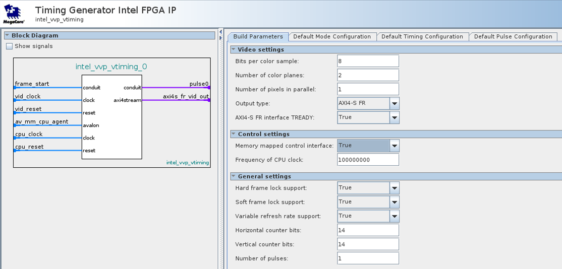
35.2. Video Timing Generator IP Parameters
These parameters are fixed at build time and can only be changed by recompiling the IP.
| Allowed Range | Description | |
|---|---|---|
| Video Settings | ||
| Number of pixels in parallel | 1 to 8 | Select the number of pixels in parallel |
| Number of color planes | 1 to 4 | Select the number of color planes per pixel |
| Bits per color sample | 6 to 16 | Select the number of bits per color sample |
| Output Type | AXI4-S FR or CV | Select the type of output bus. |
| AXI4-S FR interface TREADY 87 | True or False | Select True to include the tReady signal in the full-raster interface Select False to remove the tReady signal |
| CV Timing Signals 88 | Sync, Blank, or Both | Select which timing signals are included on the output CV bus. |
| Control Settings | ||
| Memory-Mapped Control Interface | True or False | Select True to enable the processor interface and associated signals. When False, the IP removes the processor interface, and all processor registers use default values |
| Frequency of CPU Clock 89 | 1 to 1000000000 | The frequency, in Hz, of the processor clock. |
| General Settings | ||
| Timing Word Alignment | Any or PIP-Aligned Only |
Select Any and there is no restriction on raster dimensions versus the number of pixels in parallel.
When PIP-Aligned Only, all timing parameters must be integer multiples of the pixels in parallel value. |
| Hard frame lock support | True or False | Select True to turn on hard frame lock. When False, the IP removes all frame lock support. |
| Soft frame lock support | True or False | Select True to enable soft frame lock support. 90 When False, the IP removes soft frame lock support. |
| Variable refresh rate support | True or False | Select True to enable variable refresh rate support When False, the IP removes support for variable refresh rate |
| Horizontal counter bits | 4 to 16 | The number of binary bits required to represent the maximum width of raster. For example, for a 4096 wide, set to 13. |
| Vertical counter bits | 4 to 16 | The number of binary bits required to represent the maximum height of raster. For example, for a 2048 high raster, set to 12. |
| Number of pulses | 0 to 8 | The number of additional general-purpose pulses that the IP can produce. Each additional pulse increases the gate count of this IP. If 0, the Default Pulse Configuration GUI is off. |
| Allowed Range | Description | |
|---|---|---|
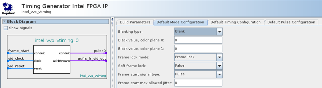
| Blanking Type | Blank or Sync | Set the style of h and v timing signals on the output. In full-raster variants, the SYNC MODE bit of the full-raster control word is set to ‘1’ to indicate blank style timing and ‘0’ to indicate sync style. If blank style is selected for a clocked video interface, the IP drives only the hBlank and vBlank signals. If sync style is selected for a clocked video interface, the IP drives only the clocked video hSync and CV vSync signals. |
| Black Value, color plane 0 | 0 to 65535 | The initial value of “black” for this color plane |
| Black Value, color plane 1 91 | 0 to 65535 | The initial value of “black” for this color plane |
| Black Value, color plane 2 91 | 0 to 65535 | The initial value of “black” for this color plane |
| Black Value, color plane 3 91 | 0 to 65535 | The initial value of “black” for this color plane |
| Frame lock mode | Freerunning Frame Lock Variable Refresh Rate |
The initial style of frame lock. For Frame Lock and Variable Refresh Rate, you must turn on the appropriate Build Parameters. |
| Soft frame lock 92 | True or False | Select True, for a soft frame lock. Select False for the hard frame lock. |
| Frame start signal type 93 | Pulse or Toggle | If you select Pulse, the IP processes the frame start input signal as a pulse. The IP uses the rising edge of the signal to indicate the start of a frame. If you select Toggle, the IP processes the frame start input signal as a toggle and the IP uses both edges of the signal to indicate the start of a frame. |
| Frame start max allowed jitter 94 | 0 to 127 | The number of video clock cycles either side of the position of the expected start of frame where an occurrence of the frame start input signal does not cause the raster to restart. If the frame start input signal occurs more than this number of video clock cycles from the point where it is expected, the IP restarts the output raster. |
| Soft lock frame start ignore | 0 to 127 | When you select True for Soft frame lock, this parameter specifies the number of lines where the frame start input signal is ignored. Unused when you turn off soft lock. |
| Soft lock frame start adjust 95 | 0 to 127 | When you select True for Soft frame lock, this parameter specifies the total number of lines used for soft lock, including the ignore lines. Unused when you select false for Soft frame lock. |
| VRR Line Mode 96 | True or False | If you select Variable Refresh Rate for Frame Lock Mode and select True for this parameter, the IP continues to produce whole lines of blanking after it produces the active pixels until it detects the frame start input signal is detected. If you select Variable Refresh Rate for Frame Lock Mode and select False for this parameter, the IP stops producing a raster when the last active line of a frame completes. The IP resumes output when it detects the frame start input signal. Unused if you do not select Variable Refresh for Frame Lock Mode. |
| Parameter | Allowed Range 97 98 | Description |
|---|---|---|
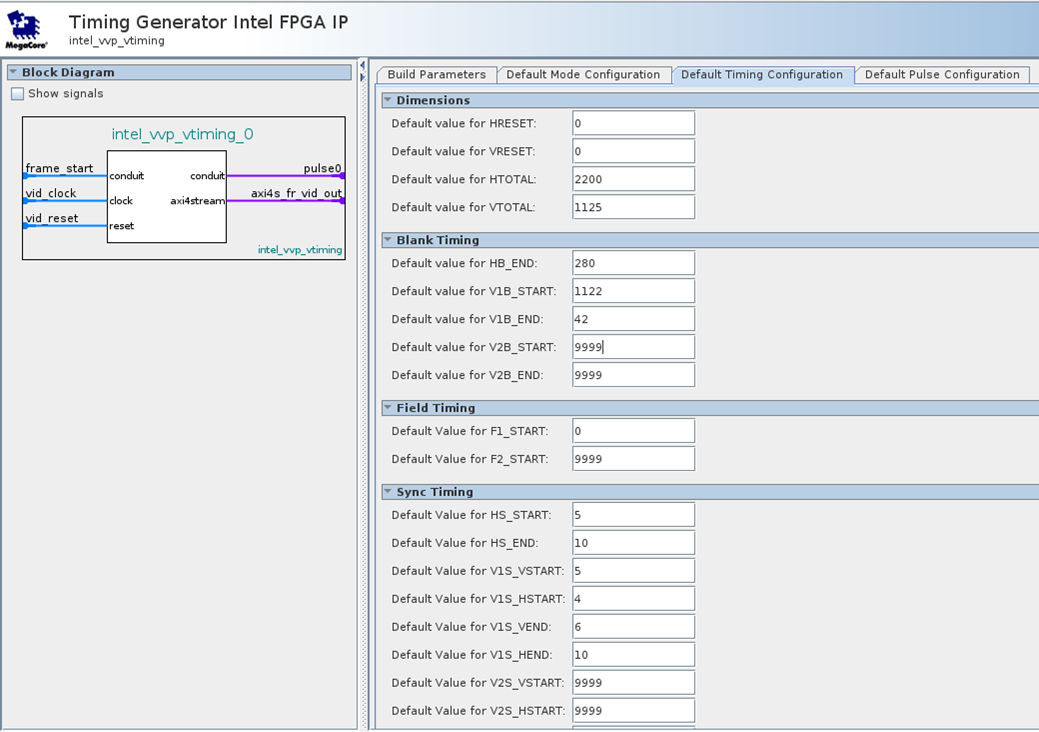
| Dimensions | ||
| Default value for HRESET | 0 to Hmax | When you select Frame lock for Frame Lock Mode, this parameter is the horizontal coordinate where the IP expects the frame start input signal. Unused if frame lock is off. |
| Default value for VRESET | 0 to Vmax | When you select Frame lock for Frame Lock Mode, this parameter is the vertical coordinate where the frame start input signal is expected. Unused if frame lock is off. |
| Default value for HTOTAL | 0 to Hmax | The width of the current raster, in pixels. |
| Default value for VTOTAL | 0 to Vmax | The width of the current raster, in pixels. |
| Blank Timing | ||
| Default value for HB_END | 0 to Hmax | First pixel of active video after horizontal blanking. Blanking always starts on pixel 0. |
| Default value for V1B_START | 0 to Vmax | First line of vertical blanking for field 1 (if interlaced) and progressive frames. |
| Default value for V1B_END | 0 to Vmax | First line of active video after vertical blanking for field 1 (if interlaced) and progressive frames. |
| Default value for V2B_START | 0 to Vmax | First line of vertical blanking for field 2 (if interlaced). |
| Default value for V2B_END | 0 to Vmax | First line of active video after vertical blanking for field 2 (if interlaced). |
| Field Timing | ||
| Default value for F1_START | 0 to Vmax | First line where f=0. |
| Default value for F2_START | 0 to Vmax | First line where f=1. |
| Sync Timing | ||
| Default value for HS_START | 0 to Hmax | First pixel of horizontal sync. |
| Default value for HS_END | 0 to Hmax | First pixel after horizontal sync. |
| Default value for V1S_VSTART | 0 to Vmax | Vertical coordinate of first pixel of vertical sync for field 1 (if interlaced) and progressive frames. |
| Default value for V1S_HSTART | 0 to Hmax | Horizontal coordinate of first pixel of vsync for field 1 (if interlaced) and progressive frames. |
| Default value for V1S_VEND | 0 to Vmax | Vertical coordinate of first active pixel after vertical sync for field 1 (if interlaced) and progressive frames. |
| Default value for V1S_HEND | 0 to Hmax | Horizontal coordinate of first active pixel after vsync for field 1 (if interlaced) and progressive frames. |
| Default value for V2S_VSTART | 0 to Vmax | Vertical coordinate of first pixel of vertical sync for field 2 (if interlaced). |
| Default value for V2S_HSTART | 0 to Hmax | Horizontal coordinate of first pixel of vsync for field 2 (if interlaced). |
| Default value for V2S_VEND | 0 to Vmax | Vertical coordinate of first active pixel after vertical sync for field 2 (if interlaced). |
| Default value for V2S_HEND | 0 to Hmax | Horizontal coordinate of first active pixel after vsync for field 2 (if interlaced). |
| Parameter | Allowed Range | Description |
|---|---|---|
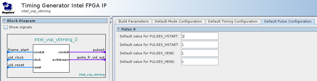
| Default value for PULSEn_VSTART | 0 to Vmax | Vertical coordinate of first pixel of pulse |
| Default value for PULSEn_HSTART | 0 to Hmax | Horizontal coordinate of first pixel of pulse |
| Default value for PULSEn_VEND | 0 to Vmax | Vertical coordinate of first active pixel after pulse |
| Default value for PULSEn_ HEND | 0 to Hmax | Horizontal coordinate of first active pixel after pulse |
This parameter is only available when you select AXI4-S FR for Output Type
This parameter is only available when you select CV for Output Type
This parameter is only available when you select True for Memory-Mapped Control Interface
Hard Frame Lock must also be True for correct operation of soft frame lock
This parameter is only available if the color plane exists. Refer to the Build Parameter tab Number of color planes
This parameter is only available if you select Frame lock for Frame Lock Mode
This parameter is only available if you select Frame lock or Variable refresh rate for Frame Lock Mode
This parameter is only available if you select Frame lock for Frame Lock Mode
This parameter is only available if you select True for Soft Frame Lock
This parameter is only available if you select Variable refresh rate for Frame Lock Mode
Vmax = (2^ Vertical counter bits) - 1
Hmax = (2^ Horizontal counter bits) - 1