Video and Vision Processing Suite Intel® FPGA IP User Guide
ID
683329
Date
9/30/2022
Public
A newer version of this document is available. Customers should click here to go to the newest version.
1. About the Video and Vision Processing Suite
2. Getting Started with the Video and Vision Processing IPs
3. Video and Vision Processing IPs Functional Description
4. Video and Vision Processing IP Interfaces
5. Video and Vision Processing IP Registers
6. Video and Vision Processing IPs Software Programming Model
7. Protocol Converter Intel® FPGA IP
8. 3D LUT Intel® FPGA IP
9. AXI-Stream Broadcaster Intel® FPGA IP
10. Chroma Key Intel® FPGA IP
11. Chroma Resampler Intel® FPGA IP
12. Clipper Intel® FPGA IP
13. Clocked Video Input Intel® FPGA IP
14. Clocked Video to Full-Raster Converter Intel® FPGA IP
15. Clocked Video Output Intel® FPGA IP
16. Color Space Converter Intel® FPGA IP
17. Deinterlacer Intel® FPGA IP
18. FIR Filter Intel® FPGA IP
19. Frame Cleaner Intel® FPGA IP
20. Full-Raster to Clocked Video Converter Intel® FPGA IP
21. Full-Raster to Streaming Converter Intel® FPGA IP
22. Generic Crosspoint Intel® FPGA IP
23. Genlock Signal Router Intel® FPGA IP
24. Guard Bands Intel® FPGA IP
25. Interlacer Intel® FPGA IP
26. Mixer Intel® FPGA IP
27. Pixels in Parallel Converter Intel® FPGA IP
28. Scaler Intel® FPGA IP
29. Stream Cleaner Intel® FPGA IP
30. Switch Intel® FPGA IP
31. Tone Mapping Operator Intel® FPGA IP
32. Test Pattern Generator Intel® FPGA IP
33. Video Frame Buffer Intel® FPGA IP
34. Video Streaming FIFO Intel® FPGA IP
35. Video Timing Generator Intel® FPGA IP
36. Warp Intel® FPGA IP
37. Design Security
38. Document Revision History for Video and Vision Processing Suite User Guide
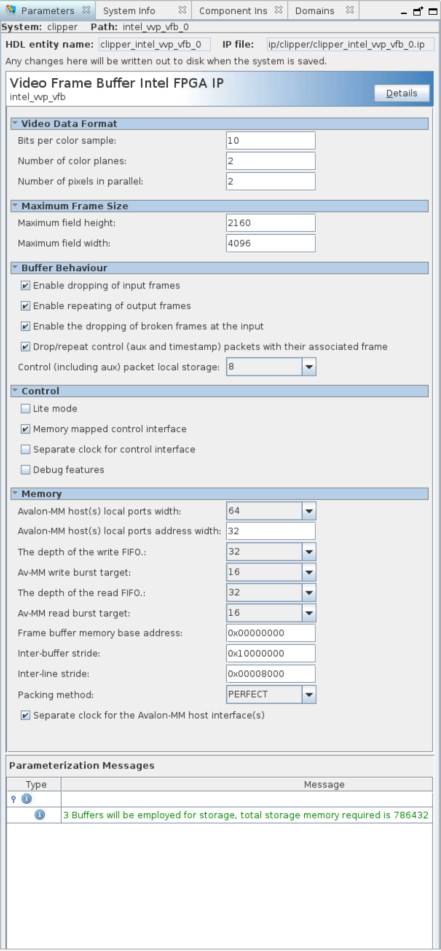
33.2. Video Frame Buffer IP Parameters
The IP offers compile-time parameters.
| Parameter | Values | Description |
|---|---|---|
| Video Data Format | ||
| Bits per color sample | 8 to 16 | Select the number of bits per color sample. |
| Number of color planes | 1 to 4 | Select the number of color planes per pixel. |
| Number of pixels in parallel | 1 to 8 | Select the number of pixels in parallel. |
| Maximum Frame Size | ||
| Maximum field height | 32 to 16384 | Select the maximum height of incoming frames. |
| Maximum field width | 32 to 16384 | Select the maximum width of incoming frames. If you use the IP exclusively to buffer frames with 420 sub-sampling, optionally halve the maximum field width entry in the GUI. Halving the entry optimizes memory footprint because of the more efficient 420 pixel-packing. |
| Buffer Behavior | ||
| Enable dropping of input frames | On or off | Turn on to drop input frames. Turn on for triple-buffering; turn off for double buffering. |
| Enable repeating of output frames | On or off | Turn on to repeat input frames. Turn on for triple-buffering; turn off for double buffering. |
| Enable the dropping of broken frames at the input | On or off | Turn on to drop broken frames. When off, the IP stores any broken frames. |
| Drop/repeat aux control metapackets with their associated frame | On or off | Turn on if you want the IP to drop and repeat any associated auxiliary control packets with their frame. When off, these packets still buffer even if the IP drops their associated frame. |
| Aux control metapacket local storage | 0, 8, 16, 32, 64, 128, 256 | Determines the total amount of local buffering provided for timestamp and other auxiliary control packets. If the IP encounters more control packets, it deletes older packets. Selecting 8 allows the IP to store 8 4-beat control packets (regardless of which frame they arrive with) or 16 2-beat, or 32 1-beat. Set this parameter to 0 if you do not require support for auxiliary control packets. |
| Control | ||
| Lite mode | On or off | Turn on to operate the frame buffer in lite mode. |
| Memory-mapped control interface | On or off | Turn on to read frame statistics and turn the frame buffer on and off using an Avalon memory-mapped interface. The memory-mapped control interface is mandatory in lite mode. |
| Separate clock for control interface | On or off | Turn on for a separate clock for the control interface. |
| Debug features | On or off | Turn on for debug features (not applicable for lite mode). |
| Memory | ||
| Avalon memory-mapped host(s) local ports width | 16, 32, 64, 128, 256, 512, 1024 | Select in bits the width of the Avalon memory-mapped host read and write ports. |
| Avalon memory-mapped host(s) local ports address width | 8 to 32 | Select in bits the width of the Avalon memory-mapped host read and write ports. It must be sufficient to fully address the last buffer. |
| The depth of the write FIFO | 32, 64, 128, 256, 512, 1024, 2048 | Specify the depth of the write FIFO buffer. Each FIFO buffer entry holds one word the width of the specified Avalon memory-mapped local port width. You must specify a FIFO depth of at least twice the specified burst target so that at least 2 bursts can be held at any one time. Increase the FIFO depth to improve resilience to latency on the Avalon memory-mapped bus. |
| Avalon memory-mapped write burst target | 2,4,8,16,32,64 | Select the burst target for writes. Longer bursts provide more efficiency on the bus but require more local storage in the write FIFO buffer. |
| The depth of the read FIFO | 32,64,128,256,512,1024,2048 | Specify the depth of the read FIFO buffer. Each FIFO buffer entry holds one word the width of the specified Avalon memory-mapped local port width. You must specify a FIFO depth of at least twice the specified burst target so that at least 2 bursts can be held at any one time. Increase the FIFO depth to improve resilience to latency on the Avalon memory-mapped bus. |
| Avalon memory-mapped read burst target | 2,4,8,16,32,64 | Select the burst target for reads. Longer bursts provide more efficiency on the bus but require more local storage in the read FIFO buffer. |
| Frame buffer memory base address | 0x0000_0000 – 0x7FFF_FFFF | Select the base address for the frame buffer to store frames. |
| Inter-buffer stride | Depends on video frame format and maximum frame size. | Set a stride (in bytes) large enough to separate frames of the specified maximum height and width. The GUI gives an error if the stride is too low. |
| Inter-line stride | Depends on video frame format and maximum frame width. | Set a stride (in bytes) large enough to separate lines of the specified maximum width. The GUI gives an error if the stride is too low. |
| Packing method | Perfect, color or pixel | Perfect packing minimizes memory footprint of stored frames but increases complexity and therefore size of the frame buffer slightly. Color packing leaves spaces in memory between colors if colors do not pack into memory words exactly. Pixel packing leaves spaces in memory between pixels if pixels do not pack into memory words exactly. |
| Separate clock for the Avalon memory-mapped host interface(s) | On or off | A separate clock allows the control and data portions of the frame buffer to run at their maximum clock frequencies. Turn on separate clocks for highest performance. |
Figure 76. Frame Buffer GUI