Video and Vision Processing Suite Intel® FPGA IP User Guide
A newer version of this document is available. Customers should click here to go to the newest version.
31.3. TMO IP Block Description
The TMO IP consists of several blocks for video processing, memory, and control. The video datapath includes a luma extractor, image statistics calculator, a soft-processor-based mapping LUT generator, CPU register interface, a contrast enhancement engine, and an image enhancer.
The luma extractor takes an RGB input frame, analyzes it, and extracts luminance. The image statistics calculator takes luma information contained in a video frame and provides a set of global and local statistic parameters regarding the contrast information on the input video frame.
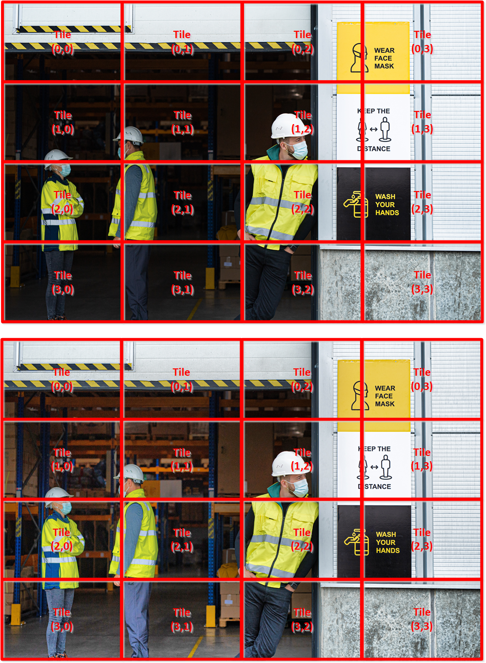
The IP collects local information about the input images in different regions on a video frame, providing the necessary granularity to properly enhance contrast in areas within the video frame that need to be adjusted.
The soft-processor-based mapping LUT generator takes the data gathered from the image statistics calculator block and generates a set of mapping transfer functions. The IP temporarily stores the mapping transfer functions in LUTs to reduce resource utilization footprint.
The contrast enhancement engine applies different amounts of mapping transfer functions in different regions of a video frame, providing the necessary granularity to properly enhance contrast in areas within the frame that you need to adjust. The TMO IP does not use external video frame buffers. Consequently, the contrast enhancement process that the IP applies to the current frame uses statistical information it collects from the previous video frame.
The image enhancer takes the image statics information gathered from the input video frame and with the generated mapping transfer function, it enhances the luma range. The image enhancer calculates a set of weights that it applied to the input RGB data to generate contrast enhanced RGB output video streams.
The embedded Nios® II processor used as a mapping LUT generator, is packaged as part of the TMO IP, and customers do not have direct access to it. An external Avalon memory-mapped processor control interface allows you to interact and configure TMO IP, giving them access to the control registers. Because of a higher level of abstraction, a set of software API allows you to easily configure and interact with the IP.