4.4.1. Using the Configure Menu
4.4.2. The System Info Tab
4.4.3. The GPIO Tab
User DIP Switch
User LEDs
Push Button Switches
4.4.4. The XCVR Tab
4.4.5. The PCIe Tab
4.4.6. The FMCA Tab
4.4.7. The FMCB Tab
4.4.8. The DDR3 Tab
4.4.9. The DDR4 Tab
4.4.10. The EEPROM Tab
4.4.11. The Power Monitor
4.4.12. The Clock Control
4.4.3. The GPIO Tab
The GPIO tab allows you to interact with all the general purpose user I/O components on your board. You can read DIP switch settings, turn LEDs on or off, and detect push button presses.
Figure 12. The GPIO Tab
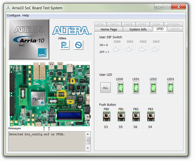
User DIP Switch
Displays the current positions of the switches in the user DIP switch bank (SW2). Change the switches on the board to see the graphical display change accordingly.
User LEDs
Displays the current state of the user LEDs for the FPGA. To toggle the board LEDs, click one of the LED [0 to 3] buttons to toggle the 4 green LEDs, or click the All button.
Push Button Switches
Read-only control displays the current state of the board user push buttons. Press a push button on the board to see the graphical display change accordingly.