4.4.12. The Clock Control
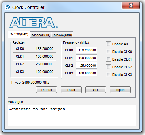
F_vco
Displays the generating signal value of the voltage-controlled oscillator.
Registers
Display the current frequencies for each oscillator.
Frequency (MHz)
Allows you to specify the frequency of the clock.
Disable all
Disable all oscillators at once.
Read
Reads the current frequency setting for the oscillator associated with the active tab.
Default
Sets the frequency for the oscillator associated with the active tab back to its default value. The default is restored by power cycling the board.
Set
Sets the programmable oscillator frequency for the selected clock to the value in the CLK0 to CLK3 controls for each Si5338. Frequency changes might take several milliseconds to take effect. You might see glitches on the clock during this time. Altera recommends resetting the FPGA logic after changing frequencies.
Import
Import register map file generated from Silicon Laboratories ClockBuilder Desktop.