DSP Builder for Intel® FPGAs (Advanced Blockset): Handbook
A newer version of this document is available. Customers should click here to go to the newest version.
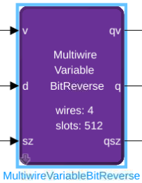
14.3.16. Multiwire Variable Bit Reverse (MultiwireVariableBitReverse)
Total data block size (2N) = number of timeslots (2 sz ) x number of wires in parallel (2M).
The wires in parallel correspond to the LSBs of the data block in the bit-reverse.
You can pair the MultiwireVariableBitReverse and the HybridVFFT block, to perform a bit reverse on variable-size parallel FFT data. The MultiwireVariableBitReverse operates a stop-and-flush protocol. On a size change you must wait for the preceding output to complete at the old size before submitting new input at the new size. When you pair the MultiwireVariableBitReverse and the HybridVFFT block, you must respect the stop-and-flush conditions of both blocks (refer to the Variable-Size Supersampled FFT with Bit-Reverse example design (demo_variable_br_hybridfft)).
The size (sz) input must be held constant while valid data is presented at the input to the block. The block holds the size output (qsz) constant during corresponding valid output from the block. The number of timeslots in the current data block is 2 sz where the total data block size is the number of timeslots multiplied by the number of wires in parallel.
| Parameter | Description |
|---|---|
| N | The maximum data block size is 2 N . |
| M | The block has 2 M wires in parallel. |
| Signal | Direction | Type | Description |
|---|---|---|---|
| v | Input | Boolean | Input valid signal. |
| d | Input | Any type | Data input. |
| sz | Input | Unsigned Integer. Width is determined by N-M |
Size input. 2 sz is the number of timeslots in the block. |
| qv | Output | Boolean | Output valid signal. |
| q | Output | Same as d | Data output. |
| qsz | Output | Same as sz | Size output. 2qsz is the number of timeslots in the block. |
The size input and outputs are different for each block. For the MultiwireVariableBitReverse block, the size input and output identify the number of timeslots. However, for the HybridFFT the size input and output is that of the FFT data block (the number of timeslots multiplied by the number of wires in parallel).
Bit Reverse Description
For example, to perform a bit reverse on data blocks of maximum size 2,048 with 4 wires in parallel, you should configure the MultiwireVariableBitReverse block with N = 11 (211 = 2048) and M = 2 (22 = 4).
The d and q connection to the block are each vectors of 4 (2 M ) elements.
The sz input (and qsz output) may take values between 2 (22 = 4) and 9 (2 N - M = 29 = 512) and identifies the number of timeslots in the current bit reversal. The datatype is uint4, which can represent the maximum value of 9.
At run time, if sz=3, the current data block has 8 (23) timeslots and each timeslot has 4 (22) wires in parallel, for a total data block size of 32 (23+2 = 25). To perform a bit reverse, first assign each element of the data block a 5-bit index 0..31, where the wires in parallel are the LSBs and the timeslots are the MSBs. The MultiwireVariableBitReverse block then outputs each element of the data block in the bit-reverse order of these indexes. The first output timeslot is of the four indexes in parallel: 0, 16, 8, 24 (i.e. in binary 00000 becomes 00000, 00001 becomes 10000, 00010 becomes 01000, 00011 becomes 11000).
As a bit reverse is self-inverse, the above transform also has a reverse interpretation.
