Multi Channel DMA Intel® FPGA IP for PCI Express User Guide
A newer version of this document is available. Customers should click here to go to the newest version.
10.1.4.3. Channel Parameters
The channel parameters window allows you to read the transmitter and receiver settings for a given channel. It has the following 3 sub-windows. Use the Lane Refresh button to read the status of the General PHY, TX Path, and RX Path sub-windows for each channel.
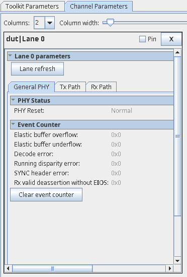
General PHY
This tab shows the reset status of the PHY.
| Parameters | Values | Descriptions | |
|---|---|---|---|
| PHY Status | PHY reset | Normal, Reset | Indicates the PHY is in reset mode. Normal: PHY is out of reset. Reset: PHY is in reset. |
| Event Counter 2 to clear the counter values. | Elastic buffer overflow | Hex value | Indicates elastic buffer overflow errors. |
| Elastic buffer underflow | Hex value | Indicates elastic buffer underflow errors. | |
| Decode error | Hex value | Indicates decode errors. | |
| Running disparity error | Hex value | Indicates running disparity errors. | |
| SYNC header error | Hex value | Indicates SYNC header errors. | |
| RX valid deassertion without EIEOS | Hex value | Indicates errors when RX valid deassertion occurs without EIEOS. |
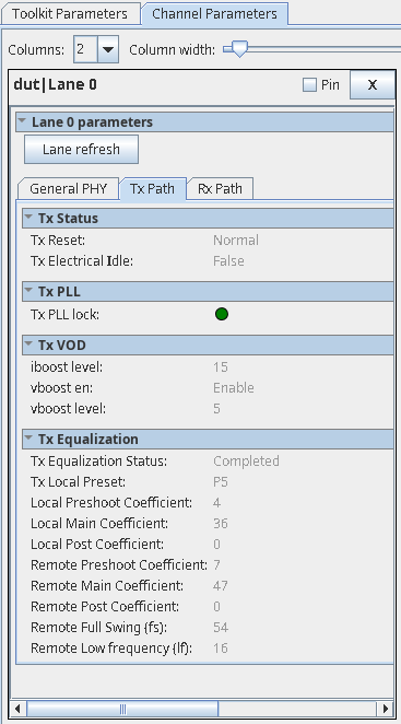
TX Path
This tab allows you to monitor the transmitter settings for the channel selected.
| Parameters | Values | Descriptions | |
|---|---|---|---|
| TX Status | TX Reset | Normal, Reset | Indicates if TX (TX datapath, TX settings) is in reset or normal operating mode. Normal: TX is in normal operating mode. Reset: TX is in reset. |
| TX Electrical Idle | True, False | Indicates if TX is in electrical idle. True: indicates TX is in electrical idle. False: indicates TX is out of electrical idle. |
|
| TX PLL | TX PLL lock | Green, Red | Indicates if TX PLL is locked. This is dependent on the PLL selected as indicated by TX PLL select.
There is one set of PLLs per Quad. The TX path of each channel reads out the PLL status corresponding to that Quad.
Green: TX PLL is locked. Red: TX PLL is not locked. |
| TX VOD | Iboost level | Gen3: 15 Gen4: 15 |
Indicates the transmitter current boost level when the TX amplitude boost mode is enabled. |
| Vboost en | Gen3: Enable Gen4: Enable |
Indicates if the TX swing boost level is enabled. Enable: TX swing boost is enabled. Disable: TX swing boost is disabled. |
|
| Vboost level | Gen3: 5 Gen4: 5 |
Indicates the TX Vboost level. | |
| TX Equalization | TX Equalization Status | Not attempted, Completed, Unsuccessful | Indicates transmitter equalization status. The TX local and remote parameters are valid only when the value of Equalization status is returned as completed, indicating equalization has completed successfully. |
| TX Local Preset | P0 to P10 | Indicates the P-tile transmitter driver preset value as requested by the link partner during the Equalization phase of link training. If the preset is not one of these values, then no value is shown. | |
| Local Pre-shoot coefficient | Depends on the coefficient requested by the link partner. |
Indicates P-tile transmitter driver output pre-emphasis (pre-cursor coefficient value). |
|
| Local main coefficient | Depends on the coefficient requested by the link partner. |
Indicates P-tile transmitter driver output pre-emphasis (main cursor coefficient value). |
|
| Local post coefficient | Depends on the coefficient requested by the link partner. |
Indicates P-tile transmitter driver output pre-emphasis (post-cursor coefficient value). |
|
| Remote Pre-shoot coefficient (†) | Depends on the transmitter driver output of the link partner. | Indicates link partner's transmitter driver's output pre-cursor coefficient value, as received by P-tile during the Equalization phase of link training. When P-tile is configured in Endpoint mode, this value corresponds to the coefficient received during Phase 2 of Equalization. |
|
| Remote main coefficient (†) | Depends on the transmitter driver output of the link partner. | Indicates link partner's transmitter driver's output main cursor coefficient value, as received by P-tile during the Equalization phase of link training. When P-tile is configured in Endpoint mode, this value corresponds to the coefficient received during Phase 2 of Equalization. |
|
| Remote post coefficient (†) | Depends on the transmitter driver output of the link partner. | Indicates the link partner's transmitter driver's output post-cursor coefficient value, as received by P-tile during the Equalization phase of link training. When P-tile is configured in Endpoint mode, this value corresponds to the coefficient received during Phase 2 of Equalization. | |
| Remote full swing (fs) (†) | Depends on the device capability of the link partner. | Indicates the full swing value used by the link partner during the Equalization phase of link training. | |
| Remote low frequency (lf) (†) | Depends on the device capability of the link partner. | Indicates the low frequency value used by the link partner during the Equalization phase of link training. |
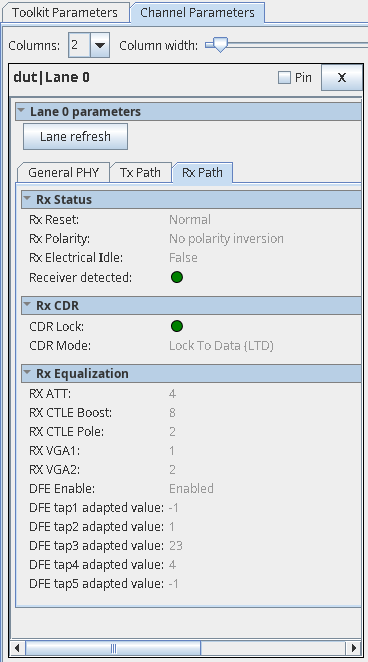
RX Path
| Parameters | Values | Descriptions | |
|---|---|---|---|
| RX Status | RX Reset | Normal, Reset | Indicates if RX (RX datapath, RX settings) is in reset or normal operating mode. Normal: RX is in normal operating mode. Reset: RX is in reset. |
| RX Polarity | No polarity inversion, Polarity inversion | Indicates RX polarity inversion for the selected lane. No polarity inversion: no polarity inversion on RX. Polarity inversion: polarity inversion on RX. |
|
| RX Electrical Idle | True, False | Indicates if RX is in electrical idle or not. True: RX is in electrical idle. False: RX is out of electrical idle. |
|
| Receiver Detected | Green, Grey | Green: Far end receiver is detected. Grey: Far end receiver is not detected. |
|
| RX CDR | CDR Lock | Green, Red | Indicates the CDR lock state. Green: CDR is locked. Red: CDR is not locked. |
| CDR Mode | Locked to Reference (LTR), Locked to Data (LTD) | Indicates the CDR lock mode. LTR: CDR is locked to reference clock. LTD: CDR is locked to data. |
|
| RX Equalization | RX ATT | Gen3: 0 Gen4: 0 |
Indicates the RX equalization attenuation level. |
| RX CTLE Boost | Gen3: 12 Gen4: 16 |
Indicates the RX CTLE boost value. |
|
| RX CTLE Pole | Gen3: 2 Gen4: 2 |
Indicates the RX CTLE pole value. |
|
| RX VGA1 | Gen3: 5 Gen4: 5 |
Indicates the RX AFE first stage VGA gain value. |
|
| RX VGA2 | Gen3: 5 Gen4: 5 |
Indicates the RX AFE second stage VGA gain value. |
|
| DFE Enable | Enable, Disable | Indicates DFE adaptation is enabled for taps 1 - 5. Enable: DFE adaptation is enabled for taps 1 - 5. Disable: DFE adaptation is disabled for taps 1 - 5. |
|
| DFE Tap1 adapted value | <-128 to 127> | Indicates the adapted value of DFE tap 1. This is a signed input (two's complement encoded). |
|
| DFE Tap2 adapted value | <-32 to 31> | Indicates the adapted value of DFE tap 2. This is a signed input (two's complement encoded). |
|
| DFE Tap3 adapted value | <-32 to 31> | Indicates the adapted value of DFE tap 3. This is a signed input (two's complement encoded). |
|
| DFE Tap4 adapted value | <-32 to 31> | Indicates the adapted value of DFE tap 4. This is a signed input (two's complement encoded). |
|
| DFE Tap5 adapted value | <-32 to 31> | Indicates the adapted value of DFE tap 5. This is a signed input (two's complement encoded). |