AN 669: Drive-On-Chip Design Example for Cyclone V Devices
9.10.4. IIR Filter
The IIR filter is a configurable second-order digital filter, based on the second-order continuous time transfer function (in Laplace notation):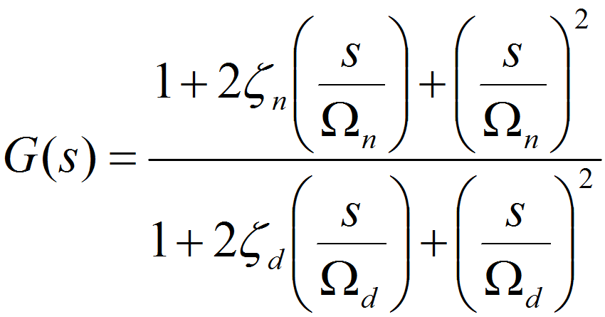
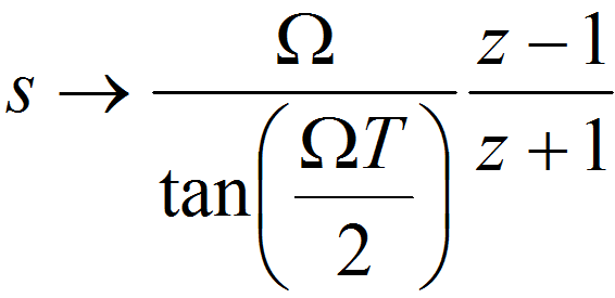
The design converts the continuous time formulation to a discrete-time formulation using a combination of the Tustin (bilinear) transformation and frequency prewarping, which ensures that the discrete time and continuous time filter characteristics match at a specified frequency Ω:
The design applies prewarping to the denominator terms with Ω = Ωd and to the numerator terms with Ω = Ωn, which ensures that the filter preserves the corner frequencies of Ωd and Ωn after the transformation.
The design applies the IIR filter to the Vd and Vq voltage signals. These signals are the final outputs of the linear control system before the trigonometric transformation to stator-fixed voltages (Vα and Vβ) and the space vector modulation (SVM) conversion to transistor gate signals.
The IIR filter is integrated into the FOC algorithm. Different DSP modes use different implementations of the FOC algorithm. Each implementation of the FOC algorithm includes a matching implementation of the IIR filter.