AN 669: Drive-On-Chip Design Example for Cyclone V Devices
ID
683466
Date
5/15/2022
Public
1. About the Drive-On-Chip Design Example for Cyclone V Devices
2. Motor Control Boards
3. Drive-On-Chip Design Example for Cyclone V Devices Features
4. Getting Started
5. Building the Design
6. Debugging and Monitoring the Drive-On-Chip Design Example with System Console
7. About the Scaling of Feedback Signals
8. Motor Control Software
9. Functional Description of the Drive-On-Chip Design Example
10. Achieving Timing Closure on a Motor Control Design
11. Design Security Recommendations
12. Reference Documents for the Drive-on-Chip Design Example
13. Document Revision History for AN 669: Drive-on-Chip Reference Design
4.1. Software Requirements for the Drive-On-Chip Design Example for Cyclone V Devices
4.2. Downloading and Installing the Drive-On-Chip Design Example for Cyclone V Devices
4.3. Setting Up the Motor Control Board with your Development Board
4.4. Programming the Hardware onto the Device
4.5. Setting Up Terminal Emulator
4.6. Downloading the HPS Software to the Device
6.1. System Console GUI Upper Pane for the Drive-On-Chip Design Example
6.2. System Console GUI Lower Pane for the Drive-On-Chip Design Example
6.3. Vibration Suppression Tab
6.4. Controlling the DC-DC Converter
6.5. Tuning the PI Controller Gains
6.6. Controlling the Speed and Position Demonstrations
6.7. Monitoring Performance
9.1. Processor Subsystem
9.2. Six-channel PWM Interface
9.3. DC Link Monitor
9.4. Drive System Monitor
9.5. Quadrature Encoder Interface
9.6. Sigma-Delta ADC Interface for Drive Axes
9.7. DC-DC Converter
9.8. Motor Control Modes
9.9. FOC Subsystem
9.10. FFTs
9.11. DEKF Technique for Battery Management
9.12. Signals
9.13. Registers
9.9.1. DSP Builder for Intel FPGAs Model for the Drive-On-Chip Designs
9.9.2. Avalon Memory-Mapped Interface
9.9.3. About DSP Builder for Intel FPGAs
9.9.4. DSP Builder for Intel FPGAs Folding
9.9.5. DSP Builder for Intel FPGAs Model Resource Usage
9.9.6. DSP Builder for Intel FPGAs Design Guidelines
9.9.7. Generating VHDL for the DSP Builder Models for the Drive-On-Chip Reference Designs
8.5. Building the HPS Preloader
Intel provides prebuilt preloader image in the software\spl_bsp\uboot-socfpga\spl directory. Only build the preloader if you change the HPS hardware settings.
- Delete the existing \software\spl-bsp directory to remove the old preloader.
- Start SoC EDS command shell.
- Start the Preloader Generator (BSP Editor) by typing the following command in SoC EDS command shell:
bsp-editor &
- In the BSP Editor, select File > New HPS BSP ...
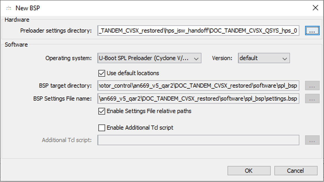
- In the New BSP window under Preloader settings directory, click ... to browse to the handoff folder.
- Select the <project_dir>/hps_isw_handoff/DOC_TANDEM_CVSX_QSYS_hps_0 directory and click Open.
The New BSP window has all the settings populated, based on the handoff folder.
- Accept the default settings and click OK. The window closes.
Figure 23. BSP Editor

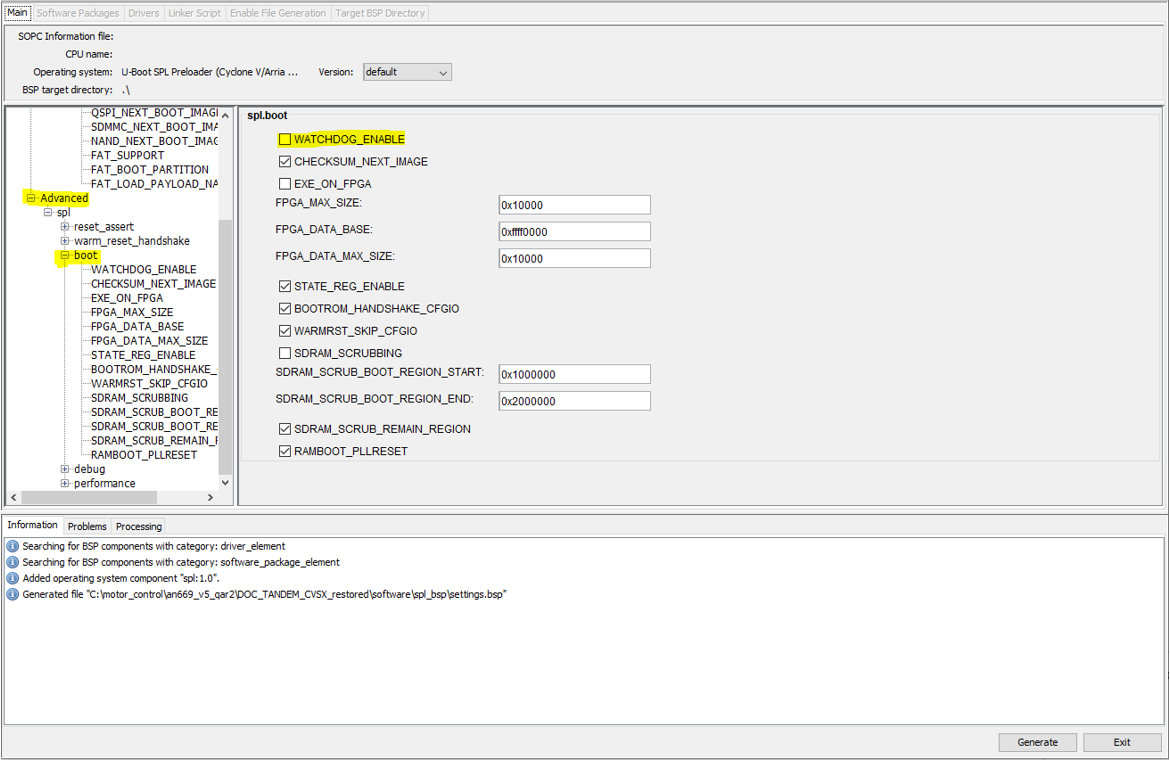
- In the BSP Editor window, expand Advanced > boot and turn off WATCHDOG_ENABLE, as the watchdog timer must be off, then click Generate.
Figure 24. BSP Editor Settings
 The message panel on the bottom indicates the status of the generation.
 - Click Exit to close the BSP Editor.
- In the SoC EDS command shell, type the following command:
cd <project_dir>/software/spl_bsp
- Type the command: make.
If you see the following error message, refer to the Unable to make preloader in Windows 10 webpage on the RocketBoards website.Figure 25. Error Message
