AN 766: Intel® Stratix® 10 Devices, High Speed Signal Interface Layout Design Guideline
ID
683132
Date
3/12/2019
Public
Intel® Stratix® 10 Devices and Transceiver Channels
PCB Stackup Selection Guideline
Recommendations for High Speed Signal PCB Routing
FPGA Fan-out Region Design
CFP2/CFP4 Connector Board Layout Design Guideline
QSFP+/zSFP/QSFP28 Connector Board Layout Design Guideline
SMA 2.4-mm Layout Design Guideline
Tyco/Amphenol Interlaken Connector Design Guideline
Electrical Specifications
Document Revision History for AN 766: Intel® Stratix® 10 Devices, High Speed Signal Interface Layout Design Guideline
Option 1: Via-In-Pad Topology
Option 2: Dog-bone with GND Cutout at BGA Pad Topology
Option 3: Micro-via Topology
GND Cutout Under BGA Pads in Fan-out Configuration
Comparison of Dog-bone with GND Cutout Under the BGA and Via-in-Pad Configurations
Trace Shape Routing at the BGA Void Area (Tear Drop Configuration)
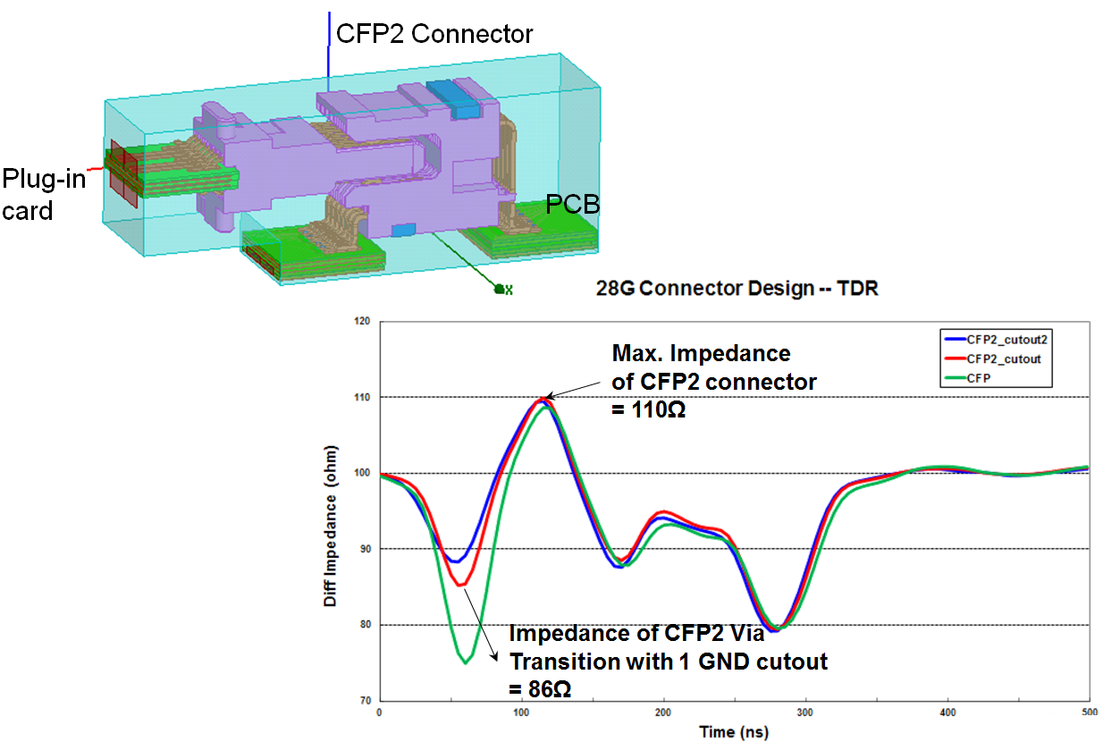
CFP2 Connector Area Layout
These are the differential TDR results from simulation including the PCB portion connected to the CFP2 connector and host compliance board. The TDR result is based on the following configuration:
- No GND cutout
- One single GND layer cutout
- Two GND layer cutouts below the CFP2 high speed signal pads
The host PCB routing has a 100 Ω impedance.
Figure 71. Simulation Structure of Partial HCB, CFP2 Connector, and Host PCB with TDR Differential Impedance ResultsThe TDR differential impedance results are from the host PCB while the HCB port is terminated.
The following figure shows the actual measured differential TDR on an Intel® Arria® 10 device populated SI board for CFP2 full channel. Two GND layers are cut out below the high speed connector pads. The reduced differential impedance is approximately 8.5 Ω at the CFP2 connector transition to the PCB.
Figure 72. Intel® Arria® 10 device PCB Layout at the CFP2 Connector
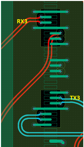
Figure 73. TDR Differential Impedance for Intel® Arria® 10 device CFP2 Full Channel Including CFP2 Connector and HCB
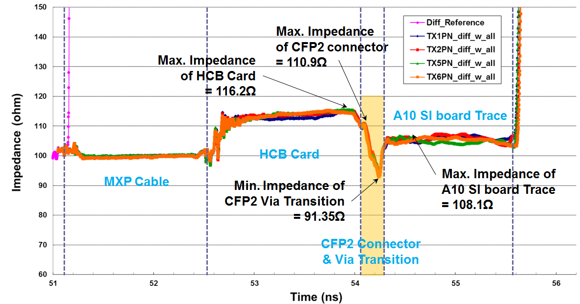
Figure 74. Insertion and Return Loss Performances of the Intel® Arria® 10 device CFP2 ChannelThis figure uses the example in Figure 72 with bare host board only.

Measured SP performances for one single TX pair and one single RX pair which both meet the CFP2 specification.