External Memory Interfaces Stratix® 10 FPGA IP User Guide
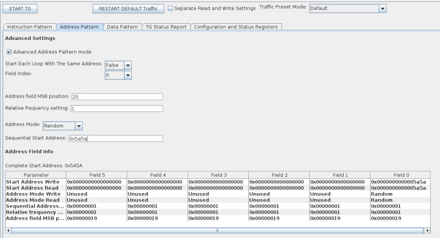
13.9.5.2.6. Address Pattern Examples - Advanced Mode
The difference in widths between amm_address_0 and mem_addr is based on the configured EMIF IP variant.
The following points apply to the examples that follow:
- A value of X indicates that a register is not used, making its value irrelevant.
- The address width (31) is the SYMBOL ADDRESS, as output from the traffic generator. In the design used for these examples, the AMM_WORD_ADDRESS_WIDTH is 26 bits. To account for this difference, the traffic generator shifts all addresses by the difference (5 bits). The examples below use this shifted address, but the external memory interface does not see this shift on its side of the ctrl_amm interface.
- The provided waveform is only a snippet of the full instruction pattern, to demonstrate the write instructions and the corresponding addresses. Not all read blocks are shown, due to space restrictions.
The width of the Avalon® address is based on the following:
- The data width on the memory side.
- Whether a configured EMIF IP is quarter rate, half rate, or full rate.
- Whether the memory interface is double data rate or quarter data rate.
Example 1: Random Address Mode
Consider the following instruction pattern:
TG_LOOP_COUNT=2 TG_WRITE_REPEAT_COUNT=1 TG_RW_GEN_IDLE_COUNT=2
TG_WRITE_COUNT=3 TG_READ_REPEAT_COUNT=1 TG_RW_GEN_LOOP_IDLE_COUNT=0
TG_READ_COUNT=3 TG_BURST_LENGTH=1
Write Start Addresses:
TG_SEQ_START_ADDR_WR  =0x5a5a
TG_SEQ_START_ADDR_WR+1=0x0000
TG_SEQ_START_ADDR_WR+2=X
       …
TG_SEQ_START_ADDR_WR+11=X
|
Read Start Addresses:
TG_SEQ_START_ADDR_RD  =0x5a5a
TG_SEQ_START_ADDR_RD+1=0x0000
TG_SEQ_START_ADDR_RD+2=X
       …
TG_SEQ_START_ADDR_RD+11=X
|
Write Address Modes:
TG_ADDR_MODE_WR=1
TG_ADDR_MODE_WR+1=3
       …
TG_ADDR_MODE_WR+5=3
|
Read Address Modes:
TG_ADDR_MODE_RD=1
TG_ADDR_MODE_RD+1=3
       …
TG_ADDR_MODE_RD+5=3
|
Sequential Address Increments:
TG_SEQ_ADDR_INCR=X
TG_SEQ_ADDR_INCR+1=X
       …
TG_SEQ_ADDR_INCR+5=X
|
Return to Start Address: TG_RETURN_TO_START_ADDR=0 |
Relative Frequencies:
TG_ADDR_FIELD_RELATIVE_FREQ=1
TG_ADDR_FIELD_RELATIVE_FREQ+1=X
       …
TG_ADDR_FIELD_RELATIVE_FREQ+5=X
|
MSB Indices:
TG_ADDR_FIELD_MSB_INDEX=AMM_WORD_ADDRESS_WIDTH-1
TG_ADDR_FIELD_MSB_INDEX+1=X
       …
TG_ADDR_FIELD_MSB_INDEX+4=X
|
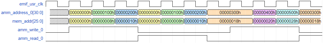
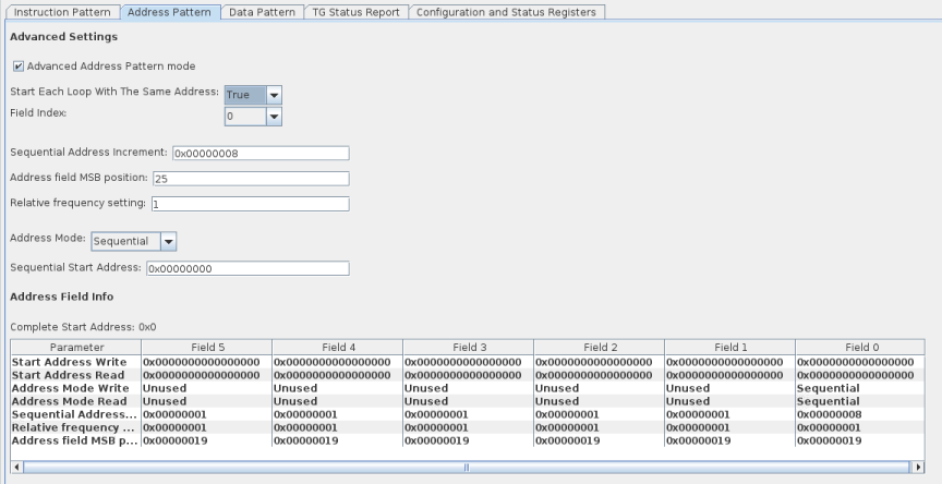
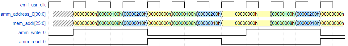
Example 2: Sequential Address Mode
Consider the following instruction pattern:
TG_LOOP_COUNT=2 TG_WRITE_REPEAT_COUNT=1 TG_RW_GEN_IDLE_COUNT=0
TG_WRITE_COUNT=3 TG_READ_REPEAT_COUNT=1 TG_RW_GEN_LOOP_IDLE_COUNT=1
TG_READ_COUNT=3 TG_BURST_LENGTH=1
Write Start Addresses:
TG_SEQ_START_ADDR_WR  =’0
TG_SEQ_START_ADDR_WR+1=’0
TG_SEQ_START_ADDR_WR+2=X
       …
TG_SEQ_START_ADDR_WR+11=X
|
Read Start Addresses:
TG_SEQ_START_ADDR_RD  =’0
TG_SEQ_START_ADDR_RD+1=’0
TG_SEQ_START_ADDR_RD+2=X
       …
TG_SEQ_START_ADDR_RD+11=X
|
Write Address Modes:
TG_ADDR_MODE_WR=2
TG_ADDR_MODE_WR+1=3
       …
TG_ADDR_MODE_WR+5=3
|
Read Address Modes:
TG_ADDR_MODE_RD=2
TG_ADDR_MODE_RD+1=3
       …
TG_ADDR_MODE_RD+5=3
|
Sequential Address Increments:
TG_SEQ_ADDR_INCR=8
TG_SEQ_ADDR_INCR+1=X
       …
TG_SEQ_ADDR_INCR+5=X
|
Return to Start Address: TG_RETURN_TO_START_ADDR=0 |
Relative Frequencies:
TG_ADDR_FIELD_RELATIVE_FREQ=1
TG_ADDR_FIELD_RELATIVE_FREQ+1=X
       …
TG_ADDR_FIELD_RELATIVE_FREQ+5=X
|
MSB Indices:
TG_ADDR_FIELD_MSB_INDEX=AMM_WORD_ADDRESS_WIDTH-1
TG_ADDR_FIELD_MSB_INDEX+1=X
       …
TG_ADDR_FIELD_MSB_INDEX+4=X
|
Example 3: Sequential Address Mode with TG_RETURN_TO_START_ADDR_1
Consider the following instruction pattern:
TG_LOOP_COUNT=2 TG_WRITE_REPEAT_COUNT=1 TG_RW_GEN_IDLE_COUNT=0
TG_WRITE_COUNT=3 TG_READ_REPEAT_COUNT=1 TG_RW_GEN_LOOP_IDLE_COUNT=1
TG_READ_COUNT=3 TG_BURST_LENGTH=1
Write Start Addresses:
TG_SEQ_START_ADDR_WR  =’0
TG_SEQ_START_ADDR_WR+1=’0
TG_SEQ_START_ADDR_WR+2=X
       …
TG_SEQ_START_ADDR_WR+11=X
|
Read Start Addresses:
TG_SEQ_START_ADDR_RD  =’0
TG_SEQ_START_ADDR_RD+1=’0
TG_SEQ_START_ADDR_RD+2=X
       …
TG_SEQ_START_ADDR_RD+11=X
|
Write Address Modes:
TG_ADDR_MODE_WR=2
TG_ADDR_MODE_WR+1=3
       …
TG_ADDR_MODE_WR+5=3
|
Read Address Modes:
TG_ADDR_MODE_RD=2
TG_ADDR_MODE_RD+1=3
       …
TG_ADDR_MODE_RD+5=3
|
Sequential Address Increments:
TG_SEQ_ADDR_INCR=8
TG_SEQ_ADDR_INCR+1=X
       …
TG_SEQ_ADDR_INCR+5=X
|
Return to Start Address: TG_RETURN_TO_START_ADDR=1 |
Relative Frequencies:
TG_ADDR_FIELD_RELATIVE_FREQ=1
TG_ADDR_FIELD_RELATIVE_FREQ+1=X
       …
TG_ADDR_FIELD_RELATIVE_FREQ+5=X
|
MSB Indices:
TG_ADDR_FIELD_MSB_INDEX+1=AMM_WORD_ADDRESS_WIDTH-1
TG_ADDR_FIELD_MSB_INDEX+1=X
       …
TG_ADDR_FIELD_MSB_INDEX+4=X
|
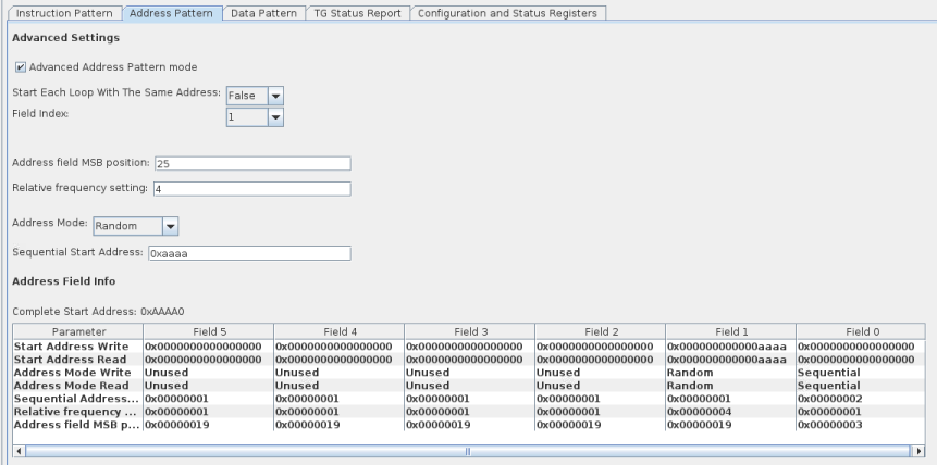
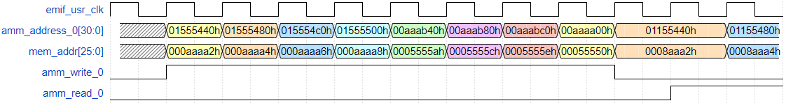
Example 4: Random Sequential Address Mode
Consider the following instruction pattern:
TG_LOOP_COUNT=1 TG_WRITE_REPEAT_COUNT=1 TG_RW_GEN_IDLE_COUNT=1
TG_WRITE_COUNT=8 TG_READ_REPEAT_COUNT=1 TG_RW_GEN_LOOP_IDLE_COUNT=1
TG_READ_COUNT=8 TG_BURST_LENGTH=1
Write Start Addresses:
TG_SEQ_START_ADDR_WR  =0x0000
TG_SEQ_START_ADDR_WR+1=0x0000
TG_SEQ_START_ADDR_WR+2=0xaaaa
TG_SEQ_START_ADDR_WR+3=0x0000
TG_SEQ_START_ADDR_WR+4=X
       …
TG_SEQ_START_ADDR_WR+11=X
|
Read Start Addresses:
TG_SEQ_START_ADDR_RD  =0x0000
TG_SEQ_START_ADDR_RD+1=0x0000
TG_SEQ_START_ADDR_RD+2=0xaaaa
TG_SEQ_START_ADDR_RD+3=0x0000
TG_SEQ_START_ADDR_RD+4=X
       …
TG_SEQ_START_ADDR_RD+11=X
|
Write Address Modes:
TG_ADDR_MODE_WR=2
TG_ADDR_MODE_WR+1=1
TG_ADDR_MODE_WR+2=3
       …
TG_ADDR_MODE_WR+5=3
|
Read Address Modes:
TG_ADDR_MODE_RD=2
TG_ADDR_MODE_RD+1=1
TG_ADDR_MODE_RD+2=3
       …
TG_ADDR_MODE_RD+5=3
|
Sequential Address Increments:
TG_SEQ_ADDR_INCR=2
TG_SEQ_ADDR_INCR+1=X
       …
TG_SEQ_ADDR_INCR+5=X
|
Return to Start Address: TG_RETURN_TO_START_ADDR=0 |
Relative Frequencies: TG_ADDR_FIELD_RELATIVE_FREQ=1 TG_ADDR_FIELD_RELATIVE_FREQ+1=4 TG_ADDR_FIELD_RELATIVE_FREQ+2=X TG_ADDR_FIELD_RELATIVE_FREQ+3=X TG_ADDR_FIELD_RELATIVE_FREQ+4=X TG_ADDR_FIELD_RELATIVE_FREQ+5=X |
MSB Indices: TG_ADDR_FIELD_MSB_INDEX=3 TG_ADDR_FIELD_MSB_INDEX+1=AMM_WORD_ADDRESS_WIDTH-1 TG_ADDR_FIELD_MSB_INDEX+4=X TG_ADDR_FIELD_MSB_INDEX+4=X TG_ADDR_FIELD_MSB_INDEX+4=X |
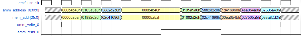
Example 5: Using Multiple Address Fields for Traversing Memory Heirarchy
Consider the following instruction pattern:
TG_LOOP_COUNT=0 TG_WRITE_REPEAT_COUNT=1 TG_RW_GEN_IDLE_COUNT=0
TG_WRITE_COUNT=1 TG_READ_REPEAT_COUNT=1 TG_RW_GEN_LOOP_IDLE_COUNT=0
TG_READ_COUNT=0 TG_BURST_LENGTH=1
Address pattern:
This address pattern uses multiple fields to traverse the memory hierarchy to isolate a specific bank group for signal integrity testing. You specify the mapping between the Avalon® control interface and the memory address and command interface using the Address Ordering parameter on the Controller tab of the parameter editor.
For example, consider a quarter-rate EMIF IP variant configured such that CTRL_DDR4_ADDR_ORDER_ENUM = DDR4_CTRL_ADDR_ORDER_CS_R_B_C_BG and the external memory is of the following format:
| Hierarchy Level | Parameter | Value of Parameter |
|---|---|---|
| Rank | MEM_DDR4_DISCRETE_CS_WIDTH (cs) |
1 |
| Bank Group | MEM_DDR4_BANK_GROUP_WIDTH (BG) |
2 |
| Bank | MEM_DDR4_BANK_ADDR_WIDTH (BA) |
2 |
| Row | MEM_DDR4_ROW_ADDR_WIDTH (R) |
15 |
| Column | MEM_DDR4_COL_ADDR_WIDTH (C) |
10 |
For this parameterization, the address bits map to the memory address and command pins on the EMIF ctrl_amm interface as follows:
| 25 | 24 | 23 | 22 | 21 | 20 | 19 | 18 | 17 | 16 | 15 | 14 | 13 | 12 | 11 | 10 | 9 | 8 | 7 | 6 | 5 | 4 | 3 | 2 | 1 | 0 |
| R | R | R | R | R | R | R | R | R | R | R | R | R | R | R | BA | BA | C | C | C | C | C | C | C | BG | BG |
In the above example, the EMIF control interface address only uses 7 column bits. Due to the quarter-rate user logic and the double data rate interface, each instruction on the ctrl_amm interface causes a burst length of 8 on the memory side. We do not explicitly address those 3 bits on the ctrl_amm interface.
In this example the goal is to generate traffic for a randomly chosen bank in bank group 3. To write to every row and column combination in this bank requires 216x27=223 unique writes on the control interface. Each TG_ADDR_FIELD_RELATIVE_FREQ register is 16 bits wide, meaning that the maximum relative frequency setting is 216-1. This maximum relative frequency does not allow access to every row and column in a bank, but does allow sufficient random coverage to test the signal integrity of each bank.
Write Start Addresses:
TG_SEQ_START_ADDR_WR  =0x0003
TG_SEQ_START_ADDR_WR+1=0x0000
TG_SEQ_START_ADDR_WR+2=0x0000
TG_SEQ_START_ADDR_WR+3=0x0000
TG_SEQ_START_ADDR_WR+4=0x0000
TG_SEQ_START_ADDR_WR+5=0x0000
TG_SEQ_START_ADDR_WR+6=0x0000
TG_SEQ_START_ADDR_WR+7=0x0000
TG_SEQ_START_ADDR_WR+8=X
        …
TG_SEQ_START_ADDR_WR+11=X
|
Read Start Addresses:
TG_SEQ_START_ADDR_RD  =0x0003
TG_SEQ_START_ADDR_RD+1=0x0000
TG_SEQ_START_ADDR_RD+2=0x0000
TG_SEQ_START_ADDR_RD+3=0x0000
TG_SEQ_START_ADDR_RD+4=0x0000
TG_SEQ_START_ADDR_RD+5=0x0000
TG_SEQ_START_ADDR_RD+6=0x0000
TG_SEQ_START_ADDR_RD+7=0x0000
TG_SEQ_START_ADDR_RD+8=X
        …
TG_SEQ_START_ADDR_RD+11=X
|
Write Address Modes: TG_ADDR_MODE_WR=0 TG_ADDR_MODE_WR+1=2 TG_ADDR_MODE_WR+2=1 TG_ADDR_MODE_WR+3=2 TG_ADDR_MODE_WR+4=3 TG_ADDR_MODE_WR+5=3 |
Read Address Modes: TG_ADDR_MODE_RD=0 TG_ADDR_MODE_RD+1=2 TG_ADDR_MODE_RD+2=1 TG_ADDR_MODE_RD+3=2 TG_ADDR_MODE_RD+4=3 TG_ADDR_MODE_RD+5=3 |
Sequential Address Increments: TG_SEQ_ADDR_INCR=X TG_SEQ_ADDR_INCR+1=1 TG_SEQ_ADDR_INCR+2=X TG_SEQ_ADDR_INCR+3=1 TG_SEQ_ADDR_INCR+4=X TG_SEQ_ADDR_INCR+5=X |
Return to Start Address: TG_RETURN_TO_START_ADDR=0 |
Relative Frequencies: TG_ADDR_FIELD_RELATIVE_FREQ=1 TG_ADDR_FIELD_RELATIVE_FREQ+1=1 TG_ADDR_FIELD_RELATIVE_FREQ+2=216-1 TG_ADDR_FIELD_RELATIVE_FREQ+3=27 TG_ADDR_FIELD_RELATIVE_FREQ+4=X TG_ADDR_FIELD_RELATIVE_FREQ+5=X |
MSB Indices: TG_ADDR_FIELD_MSB_INDEX=1 TG_ADDR_FIELD_MSB_INDEX+1=8 TG_ADDR_FIELD_MSB_INDEX+2=10 TG_ADDR_FIELD_MSB_INDEX+3=AMM_WORD_ADDRESS_WIDTH-1 TG_ADDR_FIELD_MSB_INDEX+4=X |
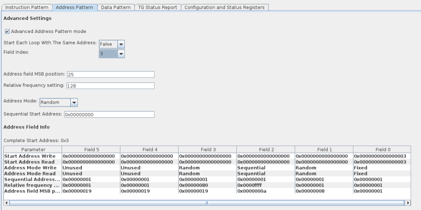
This address pattern can be performed in advanced mode only.
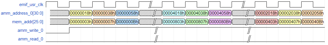
The first three writes represent the start of traffic where field 1 is incrementing every cycle. The first write after the time skip represents write number 27, as this is the first time that field 3 is incremented by 1 due to a relative frequency setting of 27. The first write after the second time skip represents write number 216, as this is the first time that a new value is generated for field 2 due to a relative frequency setting of 216-1
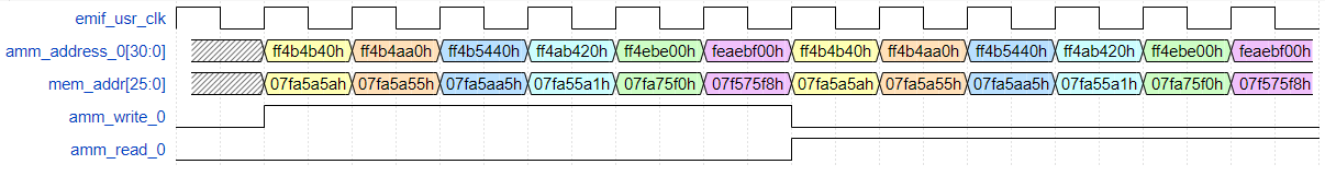
Example 6: Using All Address Fields
Consider the following instruction pattern:
TG_LOOP_COUNT=2 TG_WRITE_REPEAT_COUNT=1 TG_RW_GEN_IDLE_COUNT=0
TG_WRITE_COUNT=3 TG_READ_REPEAT_COUNT=1 TG_RW_GEN_LOOP_IDLE_COUNT=0
TG_READ_COUNT=3 TG_BURST_LENGTH=1
Address pattern:
This address pattern illustrates the abilities of the advanced mode, by tying different address bits to a variety of different address generators, each with a different relative frequency.
Write Start Addresses: TG_SEQ_START_ADDR_WR =0x000a TG_SEQ_START_ADDR_WR+1=0x0000 TG_SEQ_START_ADDR_WR+2=0x0005 TG_SEQ_START_ADDR_WR+3=0x0000 TG_SEQ_START_ADDR_WR+4=0x000a TG_SEQ_START_ADDR_WR+5=0x0000 TG_SEQ_START_ADDR_WR+6=0x0005 TG_SEQ_START_ADDR_WR+7=0x0000 TG_SEQ_START_ADDR_WR+8=0x000a TG_SEQ_START_ADDR_WR+9=0x0000 TG_SEQ_START_ADDR_WR+10=0x007f TG_SEQ_START_ADDR_WR+11=0x0000 |
Read Start Addresses: TG_SEQ_START_ADDR_RD =0x000a TG_SEQ_START_ADDR_RD+1=0x0000 TG_SEQ_START_ADDR_RD+2=0x0005 TG_SEQ_START_ADDR_RD+3=0x0000 TG_SEQ_START_ADDR_RD+4=0x000a TG_SEQ_START_ADDR_RD+5=0x0000 TG_SEQ_START_ADDR_RD+6=0x0005 TG_SEQ_START_ADDR_RD+7=0x0000 TG_SEQ_START_ADDR_RD+8=0x000a TG_SEQ_START_ADDR_RD+9=0x0000 TG_SEQ_START_ADDR_RD+10=0x007f TG_SEQ_START_ADDR_RD+11=0x0000 |
Write Address Modes: TG_ADDR_MODE_WR=1 TG_ADDR_MODE_WR+1=2 TG_ADDR_MODE_WR+2=1 TG_ADDR_MODE_WR+3=2 TG_ADDR_MODE_WR+4=1 TG_ADDR_MODE_WR+5=0 |
Read Address Modes: TG_ADDR_MODE_RD=1 TG_ADDR_MODE_RD+1=2 TG_ADDR_MODE_RD+2=1 TG_ADDR_MODE_RD+3=2 TG_ADDR_MODE_RD+4=1 TG_ADDR_MODE_RD+5=0 |
Sequential Address Increments: TG_SEQ_ADDR_INCR=X TG_SEQ_ADDR_INCR+1=5 TG_SEQ_ADDR_INCR+2=X TG_SEQ_ADDR_INCR+3=2 TG_SEQ_ADDR_INCR+4=X TG_SEQ_ADDR_INCR+5=X |
Return to Start Address: TG_RETURN_TO_START_ADDR=0 |
Relative Frequencies: TG_ADDR_FIELD_RELATIVE_FREQ=1 TG_ADDR_FIELD_RELATIVE_FREQ+1=2 TG_ADDR_FIELD_RELATIVE_FREQ+2=3 TG_ADDR_FIELD_RELATIVE_FREQ+3=4 TG_ADDR_FIELD_RELATIVE_FREQ+4=5 TG_ADDR_FIELD_RELATIVE_FREQ+5=X |
MSB Indices: TG_ADDR_FIELD_MSB_INDEX=3 TG_ADDR_FIELD_MSB_INDEX+1=7 TG_ADDR_FIELD_MSB_INDEX+2=11 TG_ADDR_FIELD_MSB_INDEX+3=15 TG_ADDR_FIELD_MSB_INDEX+4=19 |
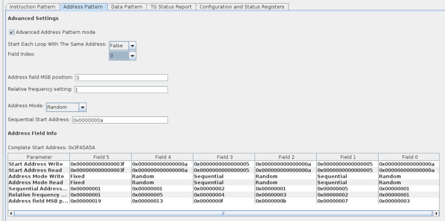
This address pattern can be performed in advanced mode only.