AN 704: FPGA-based Safety Separation Design Flow for Rapid Functional Safety Certification
ID
683720
Date
9/01/2018
Public
Design Hierarchy and safety IP partitions
Preparing the Design Example in the Intel® Quartus® Prime Software
DC Link Monitor safety IP partition
Creating a Safety IP partition for the DC Link Monitor and PLL Subsystem Component
Creating a Safety IP partition for the PWM Interface Component
Creating a Safety IP LogicLock Region for the DC Link Monitor
Creating a LogicLock Region for the PWM Interface
Creating a Fixed Size and Origin for a LogicLock Region
Removing Precomiled Netlists
Using the Intel® Quartus® Prime Incremental Compilation
Compiling the Design
The Fitter Report
Exporting Safety IP Partition
Generating Safety IP Bitstream Files
Creating a Safety IP partition for the DC Link Monitor and PLL Subsystem Component
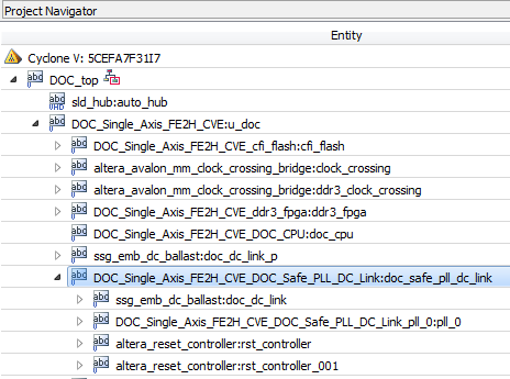
- In the Project Navigator, expand the DOC_Single_Axis_FE2H_CVE:u_doc hierarchy
- Select the entity DOC_Single_Axis_FE2H_CVE_DOC_Safe_PLL_DC_Link:doc_safe_pll_dc_link
- Right-click and select Design Partition > Set as Design Partition.
Figure 12. Selecting the Entity
 Note: A safety IP partition must include all IO pins that are directly connected to the partition.
 - Confirm a partition icon appears next to the DOC_Single_Axis_FE2H_CVE_DOC_Safe_PLL_DC_Link:doc_safe_pll_dc_link entity.
- Open the Design Partition Window:
- In the Project Navigator, select the entity DOC_Single_Axis_FE2H_CVE_DOC_Safe_PLL_DC_Link:doc_safe_pll_dc_link
- Right-click and select Design Partition > Design Partition Window.
- Ensure you strictly preserve the design partition, as required by the safety separation flow:
- In the Design Partition Window, right-click the DOC_Single_Axis_FE2H_CVE_DOC_Safe_PLL_DC_Link:doc_safe_pll_dc_link partition and select Design Partition Properties…
- Set the partition netlist type to Post-Fit.
- On the Strict Preservation tab, turn on Allow partition to be strictly preserved for safety.
- On the Advanced tab set the Fitter Preservation Level to Placement and Routing.
- Click Apply and click OK.
- Assign the safety partition I/O pins to the design partition.
Note: A safety IP partition must include all IO pins that are directly connected to the partition.
- Identify the I/O pins that are directly connected. Assign them to fixed pin locations and add these named pins to the partition by adding assignments to the project settings file (DOC_top_FE2H_CVE.qsf) using a text editor.
#Reference clock to PLL set_instance_assignment -name ENABLE_STRICT_PRESERVATION ON -to clk_50 -section_id "DOC_Single_Axis_FE2H_CVE_DOC_Safe_PLL_DC_Link:doc_safe_pll_dc_link" set_instance_assignment -name ENABLE_STRICT_PRESERVATION ON -to dc_link_Sync_Dat_VBUS -section_id "DOC_Single_Axis_FE2H_CVE_DOC_Safe_PLL_DC_Link:doc_safe_pll_dc_link" set_instance_assignment -name ENABLE_STRICT_PRESERVATION ON -to "dc_link_Sync_Dat_VBUS(n)" -section_id "DOC_Single_Axis_FE2H_CVE_DOC_Safe_PLL_DC_Link:doc_safe_pll_dc_link" #Output clocks from PLL to ADC (3 LVDS pairs) set_instance_assignment -name ENABLE_STRICT_PRESERVATION ON -to VBus_Clk -section_id "DOC_Single_Axis_FE2H_CVE_DOC_Safe_PLL_DC_Link:doc_safe_pll_dc_link" set_instance_assignment -name ENABLE_STRICT_PRESERVATION ON -to "VBus_Clk(n)" -section_id "DOC_Single_Axis_FE2H_CVE_DOC_Safe_PLL_DC_Link:doc_safe_pll_dc_link" set_instance_assignment -name ENABLE_STRICT_PRESERVATION ON -to IU_Clk -section_id "DOC_Single_Axis_FE2H_CVE_DOC_Safe_PLL_DC_Link:doc_safe_pll_dc_link" set_instance_assignment -name ENABLE_STRICT_PRESERVATION ON -to "IU_Clk(n)" -section_id "DOC_Single_Axis_FE2H_CVE_DOC_Safe_PLL_DC_Link:doc_safe_pll_dc_link" set_instance_assignment -name ENABLE_STRICT_PRESERVATION ON -to IW_Clk -section_id "DOC_Single_Axis_FE2H_CVE_DOC_Safe_PLL_DC_Link:doc_safe_pll_dc_link" set_instance_assignment -name ENABLE_STRICT_PRESERVATION ON -to "IW_Clk(n)" -section_id "DOC_Single_Axis_FE2H_CVE_DOC_Safe_PLL_DC_Link:doc_safe_pll_dc_link"Note:Several DC link monitor block signals are connected to pins of LVDS IO standard and therefore have two pins associated with each signal e.g. dc_link_Sync_Dat_VBUS and dc_link_Sync_Dat_VBUS(n).
CAUTION:All the I/O pins that connect up to a safety IP should have an explicit assignment. The Intel® Quartus® Prime software reports an error if:- a pin that connects to the safety IP does not have an assignment
- a pin with an assignment does not connect to the specified safety IP.
CAUTION:If an IO_REG group contains a pin that is assigned to a safety IP, the Intel® Quartus® Prime software reserves all the pins in the IO_REG group for this safety IP. You must assign all pins in the IO_REG group to the same safety IP; assign none of the pins in the group to nonsafety signals.