DSP Builder for Intel® FPGAs (Advanced Blockset): Handbook
A newer version of this document is available. Customers should click here to go to the newest version.
7.13.13. Cholesky-based Matrix Inversion
- Cholesky decomposition
- Triangular matrix inversion through forward substitution
- Triangular matrix multiplication
The Cholesky decomposition calculates the reciprocal values of the diagonal elements of L, which the triangular matrix inversion requires. The design propagates those values to the output interface of the Cholesky decomposition reducing resource usage and latency.
Assuming matrix A is an NxN positive-definite square matrix, Cholesky decomposition of A into lower and upper triangular matrices, L, and L H is given by:
A = LH
The inverse of Hermitian A, A -1 is:
The design performs Cholesky decomposition and calculates the inverse of L, , through forward substitution. J is a lower triangle matrix. The inverse of the input matrix requires a triangular matrix multiplication, followed by a Hermitian matrix multiplication:
The Cholesky-based matrix inversion reference design comprises a Cholseky decomposition design and a triangular matrix inversion design. Both designs are fully pipelined, with multichannel input and output streaming to maximize throughput. The size of dot-product engines in both designs are compile-time configurable according to the size of the input matrices. The datapath and control logic are split.
This design supports single-precision floating-point Cholesky matrix inversion. DSP Builder requires a single-precision floating-point input for the floating point inversion.
Matrix inversion takes multiple matrices and interleaves the inverse computations for all matrices. This method hides the latency in computing each element by pipelining inversion of a completely different channel. Multichannel designs use the idle cycles in the computation chain to process the next channel. Two buffers at the input and output of the design create channels for streaming matrices into multichannel interfaces.
| Signal | Direction | Type | Width | Description |
|---|---|---|---|---|
| Sink_Valid | Input | Boolean | 1 | Avalon streaming sink valid signal for the input matrix interface. Number of valid input = (matrix size*(matrix size + 1))/2 |
| Sink_Channel | Input | unsigned integer | 8 | Avalon streaming sink channel bus for the input matrix interface. |
| Sink_Data | Input | Single floating-point complex | 64 bit I/Q | Avalon streaming sink data bus for the input matrix interface. Lower matrix elements are streamed in column major order. |
| Source_Valid | Output | Boolean | 1 | Avalon streaming source valid signal for output interface. This signal is asserted for (size*(size+1))/2 clocks |
| Source_Channel | Output | unsigned integer | 8 | Avalon streaming source channel bus for output interface. |
| Source_Data | Output | Single floating-point complex | 64 bit I/Q | Avalon streaming source data bus for output interface. Lower matrix elements are streamed in column major order. |
Parameters
| Parameter | Description |
|---|---|
| Size of Matrix | The size of matrix to invert. |
| Channels | Number of matrices inverted in a burst. Minimum of 16 channel. |
| Latency | The period in cycles the module waits before receiving the next set of matrices. |
DSP Builder calculates the throughput of the design by setting the latency value and the system clock:
Throughput (matrix inversion per second) = System clock/Latency
Although elements of input matrices arrive in streaming format, the internal channelizer vectorizes the input matrices into several channels (the default is 16). This vectorization significantly improves the throughput.
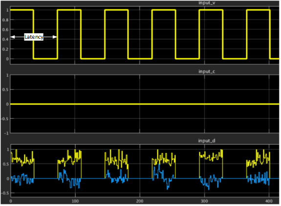
The figure shows the latency configuration parameter in the input interface including data, valid, and channel signals. In this example of 8x8 matrix inversion, the valid signal remains high for 36 clock cycles (total number of lower triangle elements of the Hermitian matrix of 8x8) and remains low for (latency – 36) cycles before inserting the next matrix elements. The minimum duration to remain low and hence the minimum latency period may vary depending on the matrix size and the pipelining required to meet timing constraints.
| Matrix Dimension | Latency in clock cycles | |
|---|---|---|
| Intel Arria 10 Devices | Intel Stratix 10 Devices | |
| 4x4 | ≥ 30 | ≥ 30 |
| 8x8 | ≥ 75 | ≥ 74 |
| 16x16 | ≥ 230 | ≥ 220 |
Performance and Resource Usage
| Matrix Dimension | Number of channels | Logic Elements (ALMs) | DSP Blocks | Memory bits | RAM blocks | Registers |
|---|---|---|---|---|---|---|
| 4x4 | 16 | 8,236 | 55 | 548,448 | 55 | 22,066 |
| 8x8 | 16 | 16,665 | 103 | 2,001,664 | 194 | 45,463 |
| 16x16 | 16 | 35,025 | 199 | 7,085,088 | 521 | 95,079 |
| Matrix Dimension | Number of channels | Target System clock (MHz) | fMAX (MHz) | ThroughputMAX |
|---|---|---|---|---|
| 4x4 | 16 | 368.64 | 468.06 | 12.2 |
| 8x8 | 16 | 368.64 | 403.88 | 5.0 |
| 16x16 | 16 | 368.64 | 392.77 | 1.67 |