External Memory Interfaces (EMIF) IP User Guide: Agilex™ 5 FPGAs and SoCs
ID
817467
Date
4/01/2024
Public
A newer version of this document is available. Customers should click here to go to the newest version.
1. About the External Memory Interfaces Agilex™ 5 FPGA IP
2. Agilex™ 5 FPGA EMIF IP – Introduction
3. Agilex™ 5 FPGA EMIF IP – Product Architecture
4. Agilex™ 5 FPGA EMIF IP – End-User Signals
5. Agilex™ 5 FPGA EMIF IP – Simulating Memory IP
6. Intel® Agilex™ 5 FPGA EMIF IP - DDR4 Support
7. Intel® Agilex™ 5 FPGA EMIF IP - LPDDR4 Support
8. Intel® Agilex™ 5 FPGA EMIF IP - LPDDR5 Support
9. Agilex™ 5 FPGA EMIF IP – Timing Closure
10. Agilex™ 5 FPGA EMIF IP – Controller Optimization
11. Agilex™ 5 FPGA EMIF IP – Debugging
12. Document Revision History for External Memory Interfaces (EMIF) IP User Guide
3.2.1. Agilex™ 5 EMIF Architecture: I/O Subsystem
3.2.2. Agilex™ 5 EMIF Architecture: I/O SSM
3.2.3. Agilex™ 5 EMIF Architecture: HSIO Bank
3.2.4. Agilex™ 5 EMIF Architecture: I/O Lane
3.2.5. Agilex™ 5 EMIF Architecture: Input DQS Clock Tree
3.2.6. Agilex™ 5 EMIF Architecture: PHY Clock Tree
3.2.7. Agilex™ 5 EMIF Architecture: PLL Reference Clock Networks
3.2.8. Agilex™ 5 EMIF Architecture: Clock Phase Alignment
3.2.9. User Clock in Different Core Access Modes
6.4.3.1. 1 Rank x 8 Discrete (Memory Down) Topology
6.4.3.2. 1 Rank x 16 Discrete (Memory Down) Topology
6.4.3.3. VREF_CA/RESET Signal Routing Guidelines for 1 Rank x 8 and 1 Rank x 16 Discrete (Memory Down) Topology
6.4.3.4. Skew Matching Guidelines for DDR4 (Memory Down) Discrete Configurations
6.4.3.5. Power Delivery Recommendation for DDR4 Discrete Configurations
6.4.3.6. DDR4 Simulation Strategy
11.1. Interface Configuration Performance Issues
11.2. Functional Issue Evaluation
11.3. Timing Issue Characteristics
11.4. Verifying Memory IP Using the Signal Tap Logic Analyzer
11.5. Generating Traffic with the Test Engine IP
11.6. Guidelines for Developing HDL for Traffic Generator
11.7. Hardware Debugging Guidelines
11.8. Create a Simplified Design that Demonstrates the Same Issue
11.9. Measure Power Distribution Network
11.10. Measure Signal Integrity and Setup and Hold Margin
11.11. Vary Voltage
11.12. Operate at a Lower Speed
11.13. Determine Whether the Issue Exists in Previous Versions of Software
11.14. Determine Whether the Issue Exists in the Current Version of Software
11.15. Try A Different PCB
11.16. Try Other Configurations
11.17. Debugging Checklist
11.18. Categorizing Hardware Issues
11.19. Signal Integrity Issues
11.20. Characteristics of Signal Integrity Issues
11.21. Evaluating Signal Integrity Issues
11.22. Skew
11.23. Crosstalk
11.24. Power System
11.25. Clock Signals
11.26. Address and Command Signals
11.27. Read Data Valid Window and Eye Diagram
11.28. Write Data Valid Window and Eye Diagram
11.29. Hardware and Calibration Issues
11.30. Memory Timing Parameter Evaluation
11.31. Verify that the Board Has the Correct Memory Component or DIMM Installed
5.1.4. Simulating the Design Example
This topic describes how to simulate the design example in Synopsys* , and Siemens EDA simulators.
To run a simulation, navigate to the simulation directory <example_design_directory>/sim/ed_sim/ and run the simulation script of your choice.
For ModelSim* SE and Siemens* EDA QuestaSim*- Intel FPGA Edition Simulators
- At the command prompt, change the working directory to the following:
<example_design_directory>/sim/ed_sim/mentor
- Invoke vsim by typing:
vsim
The system launches a terminal window where you can run the commands described in the following steps. - Run the following command in the terminal window:
source msim_setup.tcl
- Run the following command in the terminal window:
ld_debug
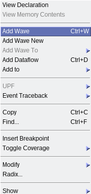
- To select a signal to observe, right-click and select Add Wave from the context menu.
- To run the simulation, type:
run -all
Upon successful completion, the simulation displays the following message:
Simulation stopped due to successful completion!
For VCS Simulator
At the command prompt, change the working directory to the following: <example_design_directory>/sim/ed_sim/synopsys/vcs
Non-interactive Mode
To run a simulation in non-interactive mode, proceed as follows:
- Type the following command on a single line:
sh vcs_setup.sh USER_DEFINED_COMPILE_OPTIONS="" USER_DEFINED_ELAB_OPTIONS="-xlrm\ uniq_prior_final" USER_DEFINED_SIM_OPTIONS=""
The system performs the simulation and displays the following message upon successful completion:
Simulation stopped due to successful completion!
Interactive Mode
To run a simulation in interactive mode, proceed as described below.
Note: If you have already generated a simv executable in non-interactive mode, delete the simv and simv.diadir files within the vcs folder.
- Open the vcs_setup.sh file in an editor and add a -debug_access+r command, as highlighted in the figure below:
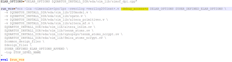
- Compile the design example by typing:
sh vcs_setup.sh USER_DEFINED_ELAB_OPTIONS="-xlrm\ uniq_prior_final" SKIP_SIM=1
- To start the simulation in interactive mode, type the following command in the terminal console:
simv -gui&