3.4.4.1. PowerPC Bus Byte Ordering
The byte positions of the PowerPC bus byte ordering are aligned with the byte positions of the Avalon® -MM interface specification; however, the bits within each byte are misaligned. PowerPC processor cores use an ascending bit ordering when the masters are connected to the interconnect. For example, a 32-bit PowerPC core labels the bus data bits 0 up to 31. A PowerPC core considers bits 0 up to 7 as byte offset 0. This layout differs from the Avalon® -MM interface specification, which defines byte offset 0 as data bits 7 down to 0. To connect a PowerPC processor to the interconnect, you must rename the bits in each byte lane as shown below.
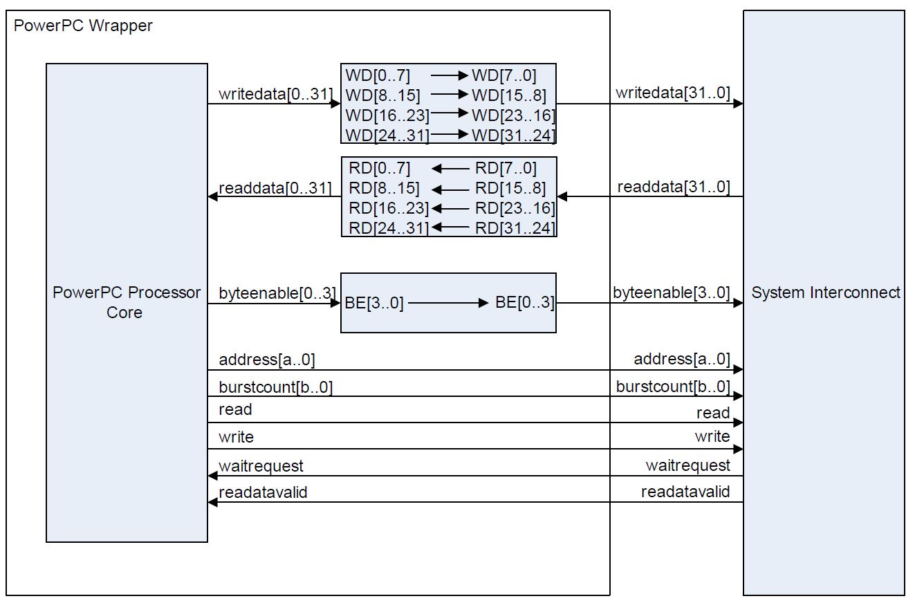
In the figure above, bit 0 is renamed to bit 7, bit 1 is renamed to bit 6, bit 2 is renamed to bit 5, and so on. By renaming the bits in each byte lane, byte offset 0 remains in the lower eight data bits. You must rename the bits in each byte lane separately. Renaming the bits by reversing all 32 bits creates a result that is not Avalon® -MM compliant. For example, byte offset 0 would shift to data bits 31 down to 24, not 7 down to 0 as required.