4.3.2.1. Adding the MPU Hardware
To add an MPU to your system, you must use a Nios® II/f core. In Platform Designer, enable the MPU by turning on Include MPU in the Core Nios® II tab of the Nios® II parameter editor interface, as shown in below.

Use the MMU and MPU Settings tab, as shown below, to configure the MPU.
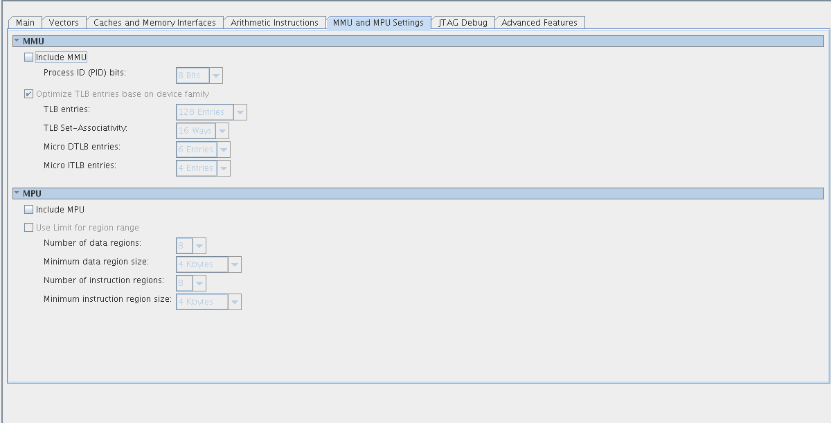
| Option | Allowed Values | Default Value |
|---|---|---|
| Use Limit for Region Range | Off or On | Off |
| Number of Data Regions | 2—32 | 8 |
| Minimum Data Region Size | 256 bytes—1 MB | 4 KB |
| Number of Instruction Regions | 2—32 | 8 |
| Minimum Instruction Region Size | 256 bytes—1 MB | 4 KB |
You can configure the MPU to define the size of its memory regions in either of the following ways:
- Define region size by specifying an address mask
- Define region size by specifying the end address
By default, the MPU defines region sizes with an address mask. To define region sizes with an end address, turn on Use Limit for Region Range. For detailed information about the two methods of specifying region size, refer to “MPU Register Details” section.
The minimum region size is crucial to understanding MPU run-time configuration. The minimum region size, <min_region>, specifies the granularity of the MPU memory map. The size of any particular memory region must be an integer multiple of <min_region>.
Most of the MPU parameters controlled by software are based on the minimum region size. You can specify separate values of <min_region> for data and instruction regions.