Serial Lite III Streaming Intel® Stratix® 10 FPGA IP Design Example User Guide
ID
683341
Date
11/01/2021
Public
A newer version of this document is available. Customers should click here to go to the newest version.
1. Quick Start Guide
2. Detailed Description for Intel® Stratix® 10 H-tile and L-tile Serial Lite III Streaming Standard Clocking Mode Design Example
3. Detailed Description for Intel® Stratix® 10 H-tile and L-tile Serial Lite III Streaming Advanced Clocking Mode Design Example
4. Detailed Description for Intel® Stratix® 10 E-tile Serial Lite III Streaming Standard Clocking Mode Design Example
5. Detailed Description for Intel® Stratix® 10 E-tile Serial Lite III Streaming Advanced Clocking Mode Design Example
6. Serial Lite III Streaming Intel® Stratix® 10 FPGA IP Design Example User Guide Archives
7. Document Revision History for Serial Lite III Streaming Intel® Stratix® 10 FPGA IP Design Example User Guide
5.5. Hardware Testing
After you download the design and the accompanying software into the FPGA, you can test the design through an interactive session. The interactive session provides helpful statistics, and enables you to control various aspects of the design.
You can control the following operations by entering the numbers listed below:
- 0) Toggle Loopback Mode - Toggles TX to RX serial loopback path within the transceiver or external loopback mode. The loopback mode is specified in the interactive session. Disable the traffic generator/checker before switching loopback modes to avoid transmission error.
- 1) Enable Data Generator/Checker - Enables the traffic generator and start sending out data.
- 2) Disable Data Generator/Checker - Disables traffic generation.
- 3) Reset Source Core - Resets the source core and traffic generator.
- 4) Reset Sink Core - Resets the sink core and traffic checker.
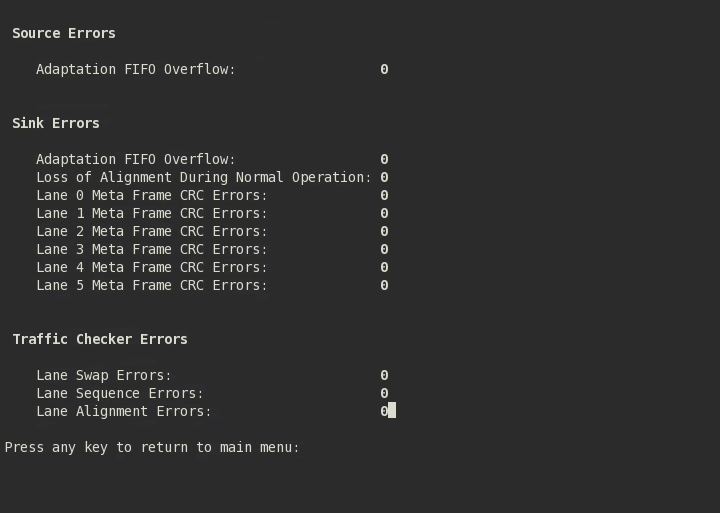
- 5) Display Error Details - Displays the error statistics.
- 6) Toggle Burst/Continuous Mode - Resets the source and sink MACs and switches the traffic generator to generate a burst (multiple burst packet data) or continuous (single continuous data) traffic stream. By default, the design example is set to burst mode. When in continuous mode, the burst count is always 1. Disable the data generator/checker before switching mode to avoid transmission error.
- 7) Toggle CRC Error Insertion - Turns CRC error injection off or on (for all lanes). By default, the design example has CRC error injection turned off.
Note: Options 8 and 9 applicable only in standard clocking mode.
Figure 46. Example of a Successful Hardware Test When Data Generator/Checker is EnabledTest report with zero errors indicates a successful data transmission.

