External Memory Interfaces Agilex™ 7 F-Series and I-Series FPGA IP User Guide
11.9.5.3. Data Pattern and Byte Enable
Example:
This example assumes the following conditions:
- DQ Width: x72 (without ECC enabled)
- Memory Protocol: DDR4
- DQ/DQS: 8
- Rate: Quarter-rate
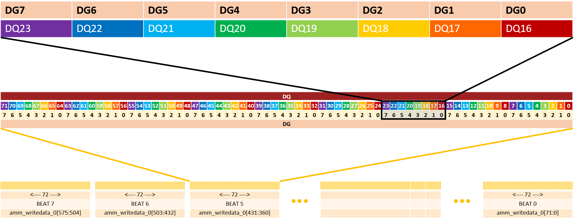
Because there are 8 DQ/DQS, there are 8 data generators, meaning that DQ0, DQ8, DQ16 … DQ56, and DQ64 share the same data generator.
In this example, each data transfer on the ctrl_amm interface is 576 bits wide. For the purpose of this example, we focus on beat 5 of the transfer, as seen on the memory side:
- DQ[0] corresponds to beat 5 of the memory bus burst and it takes bit5 from DG0
- DQ[1] corresponds to beat 5 of the memory bus burst and it takes bit5 from DG1
- ...
- DQ[3] corresponds to beat 5 of the memory bus burst and it takes bit5 from DG3
- ...
- DQ[8] corresponds to beat 5 of the memory bus burst and it takes bit5 from DG0
- DQ[9] corresponds to beat 5 of the memory bus burst and it takes bit5 from DG1

For each data generator, you can create a unique data pattern by configuring the start seed (32 bits wide) and pattern mode by writing to the TG_DATA_SEED register and the TG_PPPG_SEL register, respectively. Refer to Configuration and Status Registers for the supported options.
The following table illustrates examples of data patterns that can be generated on each data generator by configuring the TG_DATA_SEED and TG_PPPG_SEL registers.
| Mode | Description |
|---|---|
| Fixed | The data pattern is constant. Only the lowest TG_DATA_RATE_WIDTH_RATIO bits are used – each one representing one beat on that pin. Example: A seed of 0x76543210 for DG0, where TG_DATA_RATE_WIDTH_RATIO=8 results in the following pattern seen on DQ0, sequentially: 
|
| PRBS7 | Pseudorandom Binary Sequence. Uses the 8 least-significant bits (LSB) of the input seed, and the monic polynomial: x7 + x6 + 1 A seed of ‘0 produces no unique patterns. |
| PRBS15 | Pseudorandom Binary Sequence. Uses the 16 least-significant bits of the input seed, and the monic polynomial: x15 + x14 + 1 A seed of ‘0 produces no unique patterns. |
| PRBS31 | Pseudorandom Binary Sequence. Uses all 32 bits of the input seed, and the monic polynomial: x31 + x28 + 1 A seed of ‘0 produces no unique patterns. |
| Rotating (custom) | The data pattern on the pin is 32 bits long, as specified by the user. The pattern appears on the pin least-significant bit to most-significant bit. Example: A seed of 0x76543210 for DG0 results in the following pattern seen on DQ0, sequentially: 
|
There is one byte-enable generator for each byte in the interface. The byte-enable generator options are identical to the data generator options.