5.5. S-Parameters
It is difficult to define voltages or currents in transmission lines and to measure them at microwave frequencies, because direct measurements usually involve the magnitude (inferred from power) and phase of a wave traveling in a given direction or the standing wave. Thus, equivalent voltages and currents, and the related impedance and admittance matrices, become somewhat of an abstraction when dealing with high-frequency networks.
A representation more consistent with direct measurements, and with the ideas of incident, reflected, and transmitted waves, is provided by the scattering matrix (S-parameters). S-parameters are often used to quantify the impedance, total losses, input return loss, insertion loss, and isolation and crosstalk for the different transmission lines structures. These concepts are most useful at those frequencies where you must consider distributed rather than lumped parameters.
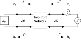
To understand S-parameters, consider the two-port network shown in Figure 85. The network can contain a transmission line or any linear time invariant component. The incident voltages at ports 1 and 2 are E11 and E12; and the reflected voltages are ER1 and ER2. Z0 is the characteristic impedance of the transmission line. ZS and ZL are the source and the load impedances.
Taking the incident and reflected voltage waves on each side of the two port network and dividing them by the square root of the characteristic impedance, Z0, results in new variables (a1, a2, b1, and b2), which are the normalized voltage wave amplitudes at each port.
The square of the magnitude of a1 (| a1|2) represents the incident power in port 1, and (| b1|2) represents the reflected power from this port. The same relations apply to port 2.
The resulting parameters relate the scattered wave (reflected wave) from the network to the incidents waves. These parameters are called S-parameters and are defined by:
Where, S11 is the input reflection coefficient, S21 is the forward transmission through the network, S12 is the reverse transmission through the network, and S22 is the output reflection coefficient.
The measurement setup for S-parameters is shown in Figure 86 and Figure 87. Apply the following conditions for these measurements:

For example, to measure S11, ensure that a2 = 0. Do this by making sure that there is no reflection from the load (in other words, set ZL = Z0).
- a1=EI1/√Z0 a2=EI2/√Z0
- b1=ER1/√Z0 b2=EI2/√Z0
- b1=S11a1+S12a2
- b2=S21a1+S22a2
- S11=(a2/b1) | a2=0
- S21=(b2/a1) | a2=0
- S12=(b1/a2) | a1=0
- S22=(b2/a2) | a1=0