Agilex® 7 FPGA F-Series Transceiver-SoC Development Kit User Guide
4.4. Control on-board power regulator through Power Monitor GUI
The Power Monitor GUI reports most power rails voltage, current, and power information on the board. You can fine-tune some regulators’ output voltage by Power Monitor GUI. It also collects temperature from FPGA SDM, FPGA core, E-Tile, P-tile, power modules and diode assembled on PCB.
The Power Monitor GUI communicates with system Intel® MAX® 10 through either USB port CN1 or J19. System Intel® MAX® 10 monitors and controls power regulator, temperature/voltage/current sensing chips through a 2-wire serial bus.
The instructions to run Power Monitor GUI are stated in the Running the BTS GUI section. It can also be started with the BTS GUI icon Power.
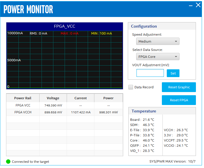
Configuration
Speed Adjustment: Adjust the update rate of current curve
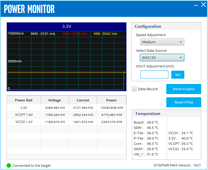
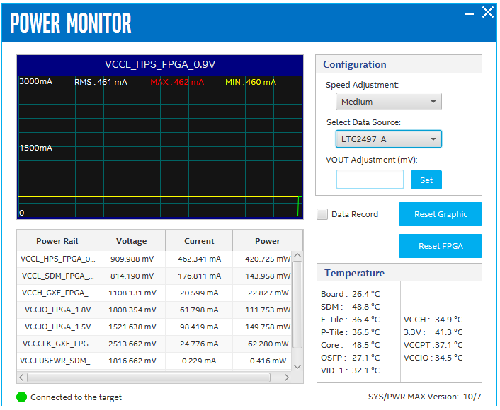
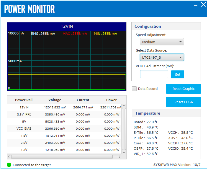
Select Data Source: Switch between different monitor targets
Vout Adjustment (mV): Fine tune each smart regulator module output within +/-7% range. Select Power Rail, fill in the box, and press the Set button.
Temperature
Board: PCB surface temperature near U31
SDM/E-tile/P-tile/Core: FPGA die internal temperature sense diode (TSD)
QSFP: Diode assembled on PCB and close to QSFP/QSFPDD modules
VID_1/VCCH/3.3V/VCCPT/VCCIO: regulator U54/U57/U53/U58/U59 internal TSD. No on-board current measurement circuit for 3.3V_PRE, 5V, VCC_BIAS, 1.8V, 2.5V and 1.2V