Multi Channel DMA Intel® FPGA IP for PCI Express* Design Example User Guide
A newer version of this document is available. Customers should click here to go to the newest version.
3.5.10.3. Ping Test
- Configure the number of channels supported on the device. It must be consistent with the number set in the IP Parameter Editor. However, you have an option to use less than the maximum available channels.
To check the number of channels supported, run the following command:
$ ethtool -l ifc_mcdma0
To set the number of channels to be used, run the following command:
$ sudo ethtool -L <device> rx <chnls> tx <chnls>
In a design with two physical functions, each allocated 16 channels, the following command set is used to configure a single channel:
$ sudo ethtool -L ifc_mcdma0 rx 1 tx 1
$ sudo ethtool -L ifc_mcdma1 rx 1 tx 1
- Configure the MTU value. Select the MTU value so that the sum of the MTU value and the Ethernet header length is aligned to 64.
Use the following command to set the MTU value:
$ ifconfig ifc_mcdma0 mtu <mtu value>
For example, the following command sets the MTU value as 1500 (standard MTU size).
 $ sudo ifconfig ifc_mcdma0 mtu 1500
 $ sudo ifconfig ifc_mcdma1 mtu 1500
- Configure the device communication. Configure for PF-PF communication by using the debugfs interface. The Avalon-ST device-side packet loopback design example has the provision to switch the packets from one channel to another.
Configure the communication from PF0 to PF1 and PF1 to PF0:
$ echo src_chnl_no | sudo tee /sys/kernel/debug/ifc_mcdma_config/src_chnl
$ echo dst_chnl_no | sudo tee /sys/kernel/debug/ifc_mcdma_config/dst_chnl
$ echo 1 | sudo tee /sys/kernel/debug/ifc_mcdma_config/update
For example, to configure a loopback between PF0 and PF1:
Note: The physical channel number should be considered based on the design example configuration on channels per PF/VF function. In the example below, PF0 has channels assigned from 0-15 and PF1 has channels assigned from 16-31.- Configure the communication from PF0 (H2D queue) to PF1 (D2H queue).
	$ echo 0 | sudo tee /sys/kernel/debug/ifc_mcdma_config/src_chnl
	$ echo 16 | sudo tee /sys/kernel/debug/ifc_mcdma_config/dst_chnl
	$ echo 1 | sudo tee /sys/kernel/debug/ifc_mcdma_config/update
- Configure the communication from PF1 (H2D queue) to PF0 (D2H queue).
$ echo 16 | sudo tee /sys/kernel/debug/ifc_mcdma_config/src_chnl
$ echo 0 | sudo tee /sys/kernel/debug/ifc_mcdma_config/dst_chnl
$ echo 1 | sudo tee /sys/kernel/debug/ifc_mcdma_config/update
Display the configuration:
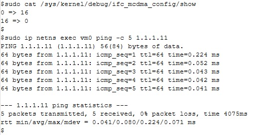
$ sudo cat /sys/kernel/debug/ifc_mcdma_config/show
Expected output:
0 → 16
16 → 0
- Configure the communication from PF0 (H2D queue) to PF1 (D2H queue).
- Ping test using the name space environment: use the following procedure to create name spaces and execute the commands.
- Stop the network manager by using the following command:
$ sudo systemctl stop NetworkManager.service
- Create the name spaces:
$ ip netns add <VM name>
For example:
$ sudo ip netns add vm0
$ sudo ip netns add vm1
- Assign the interface to name spaces using the following command:
$ sudo ip link set <interface> netns <namespace>
For example:
$ sudo ip link set ifc_mcdma0 netns vm0
$ sudo ip link set ifc_mcdma1 netns vm1
- Bring up the interface:
$ ip netns exec vm0 ifconfig <interface> up
For example:
$ sudo ip netns exec vm0 ifconfig ifc_mcdma0 up
$ sudo ip netns exec vm1 ifconfig ifc_mcdma1 up
- Assign the IP address by running the following commands:
$ ip netns exec <namespace> ip addr add <ipaddr> dev <interfacename>
For example:
$ sudo ip netns exec vm0 ip addr add 1.1.1.10/24 dev ifc_mcdma0
$ sudo ip netns exec vm1 ip addr add 1.1.1.11/24 dev ifc_mcdma1
- Stop the network manager by using the following command:
- Perform a ping from one interface to another interface:
ip netns exec <namespace> ping <ip address>
Run the following command to perform a ping with five packets:
$ sudo ip netns exec vm0 ping -c 5 1.1.1.11
Figure 54. Ping Test Results