AN 773: Drive-On-Chip Design Example for Intel® MAX® 10 Devices
ID
683072
Date
7/26/2023
Public
1. About the Drive-On-Chip Design Example for Intel® MAX® 10 Devices
2. Features of the Drive-on-Chip Design Example for Intel® MAX® 10 Devices
3. Getting Started with the Drive-On-Chip Design Example for Intel® MAX® 10 Devices
4. Rebuilding the Drive-On-Chip Design Example for Intel® MAX® 10 Devices
5. About the Scaling of Feedback Signals
6. Motor Control Software
7. Functional Description of the Drive-on-Chip Design Example
8. Achieving Timing Closure on a Motor Control Design
9. Design Security Recommendations
10. Reference Documents for the Drive-on-Chip Design Example
11. Document Revision History for AN 773: Drive-on-Chip Design Example for Intel® MAX® 10 Devices
3.1. Software Requirements for the Drive-On-Chip Design Example for Intel® MAX® 10 Devices
3.2. Hardware Requirements for the Drive-On-Chip Design Example for Intel® MAX® 10 Devices
3.3. Downloading and Installing the Design
3.4. Setting Up the Motor Control Board with your Development Board for the Drive-On-Chip Design Example for Intel® MAX® 10 Devices
3.5. Importing the Drive-On-Chip Design Example Software Project
3.6. Configuring the FPGA Hardware for the Drive-On-Chip Design Example for Intel® MAX® 10 Devices
3.7. Programming the Nios II Software to the Device for the Drive-On-Chip Design Example for Intel® MAX® 10 Devices
3.8. Applying Power to the Power Board
3.9. Debugging and Monitoring the Drive-On-Chip Design Example with System Console
3.10. System Console GUI Upper Pane for the Drive-On-Chip Design Example
3.11. System Console GUI Lower Pane for the Drive-On-Chip Design Example
3.12. Controlling the DC-DC Converter
3.13. Tuning the PI Controller Gains
3.14. Controlling the Speed and Position Demonstrations
3.15. Monitoring Performance
4.1. Changing the Intel® MAX® 10 ADC Thresholds or Conversion Sequence
4.2. Generating the Qsys System
4.3. Compiling the Hardware in the Intel Quartus Prime Software
4.4. Generating and Building the Nios II BSP for the Drive-On-Chip Design Example
4.5. Software Application Configuration Files
4.6. Compiling the Software Application for the Drive-On-Chip Design Example
4.7. Programming the Design into Flash Memory
7.1. Processor Subsystem
7.2. Six-channel PWM Interface
7.3. DC Link Monitor
7.4. Drive System Monitor
7.5. Quadrature Encoder Interface
7.6. Sigma-Delta ADC Interface for Drive Axes
7.7. Intel® MAX® 10 ADCs
7.8. ADC Threshold Sink
7.9. DC-DC Converter
7.10. Motor Control Modes
7.11. FOC Subsystem
7.12. DEKF Technique
7.13. Signals
7.14. Registers
7.11.1. DSP Builder for Intel FPGAs Model for the Drive-on-Chip Designs
7.11.2. Avalon Memory-Mapped Interface
7.11.3. About DSP Builder for Intel FPGAs
7.11.4. DSP Builder for Intel FPGAs Folding
7.11.5. DSP Builder for Intel FPGAs Model Resource Usage
7.11.6. DSP Builder for Intel FPGAs Design Guidelines
7.11.7. Generating VHDL for the DSP Builder Models for the Drive-on-Chip Designs
3.4. Setting Up the Motor Control Board with your Development Board for the Drive-On-Chip Design Example for Intel® MAX® 10 Devices
To prevent damage to the motor control board, ensure development board and power board are turned off and do not apply power until you have made all connections.
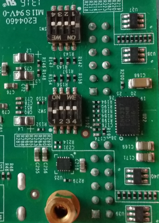
- Ensure DIP SW2 is set to OFF-ON-ON-ON.
Figure 6. DIP SW2 SettingDIP SW2 is on the lower side of the board.
- Connect the power board to the development board using the HSMC connector.
For the optional estimation of SOC, connect the battery pack to connector J1 on the Tandem Motion-Power 48 V Board.
- Connect the development board ADC connector to J20 on the power board.
Figure 7. Correct Cable Direction from Development Board to Tandem Motion-Power 48 V Board
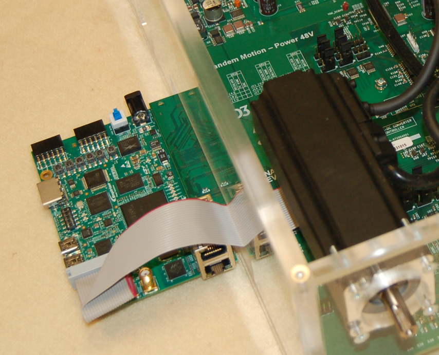
- Connect a USB cable from the USB connector J12 on the development board to your computer.
- Apply power to the development board.