AN 773: Drive-On-Chip Design Example for Intel® MAX® 10 Devices
1. About the Drive-On-Chip Design Example for Intel® MAX® 10 Devices
Supported FPGA Development Kits
The design supports the Rev C (or later) Intel® MAX® 10 10M50 FPGA Development Kit. You can modify the design to run it on other Intel FPGA development kits that have an HSMC connector.
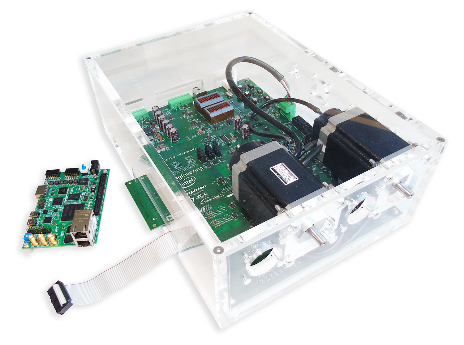
Supported Motor Control Boards
| Board | Vendor | Website | Power Stage | Sample Rate (kHz max) | Supported Feedback |
|---|---|---|---|---|---|
| Tandem Motion-Power 48 V Board | Terasic | www.terasic.com | MOSFET | 125 | Quadrature encoder, resolver, sensorless, trapezoidal |
The design requires you to attach a power board to the FPGA development kit. The power board must, at a minimum, implement the motor drive electronics (e.g., IGBT or MOSFET switches), current and voltage feedback signal conditioning and DC link power bus to provide power to the motor via the inverter. The design requires position feedback for some control algorithms.
AC and Servo Drive Systems
AC and servo drive system designs comprise multiple distinct but interdependent functions to realize requirements to meet the performance and efficiency demands of modern motor control systems. The system's primary function is to efficiently control the torque and speed of the AC motor through appropriate control of power electronics. A typical drive system includes:
- Flexible pulse-width modulation (PWM) circuitry to switch the power stage transistors appropriately
- Motor control loops for single- or multiaxis control
- Industrial networking interfaces
- Position encoder interfaces
- Current, voltage, and temperature measurement feedback elements.
- Monitoring functions, for example, for vibration suppression.
The system requires software running on a processor for high-level system control, coordination, and management.
Intel® MAX® 10 Devices and DSP Builder for Intel FPGAs
Intel® MAX® 10 devices offer high-performance fixed- and floating-point DSP functionality, and Nios II soft processors. Intel® MAX® 10 FPGA devices offer a scalable and flexible platform for integration of single- and multiaxis drives on a single FPGA. The design comprises IP, software libraries, and a hardware platform. The design demonstrates DSP Builder for Intel FPGAs and Qsys for creating the the Avalon® Memory-Mapped interface between IP and the processor. The design includes all software and IP components. You can extend and customize the design to meet your own application needs. The design supports partitioning of algorithms between software running on an integrated processor and IP performing portions of the motor control algorithm in the FPGA, to accelerate performance. For example, depending on the performance requirements of your system or the number of axes you need to support, you may implement the field-oriented control (FOC) loop in hardware designed using DSP Builder for Intel FPGAs, or in software on the Nios II processor. The design allows you to connect to the motor and power stages through on chip or off-chip ADCs, feedback encoder devices and transistor gate drive circuitry. You can connect to higher-level automation controllers by adding off-the-shelf IP, for example for industrial Ethernet or CAN.
DSP Builder for Intel FPGAs provides a MATLAB Simulink* based work flow that allows you to create hardware-optimized fixed-latency implementations of algorithms without requiring HDL or hardware programming skills. The design provides fixed- and floating-point examples of the FOC algorithm. You can use the DSP Builder folding feature to reduce the resource usage of the logic compared to a direct parallel implementation.