AN 773: Drive-On-Chip Design Example for Intel® MAX® 10 Devices
ID
683072
Date
7/26/2023
Public
1. About the Drive-On-Chip Design Example for Intel® MAX® 10 Devices
2. Features of the Drive-on-Chip Design Example for Intel® MAX® 10 Devices
3. Getting Started with the Drive-On-Chip Design Example for Intel® MAX® 10 Devices
4. Rebuilding the Drive-On-Chip Design Example for Intel® MAX® 10 Devices
5. About the Scaling of Feedback Signals
6. Motor Control Software
7. Functional Description of the Drive-on-Chip Design Example
8. Achieving Timing Closure on a Motor Control Design
9. Design Security Recommendations
10. Reference Documents for the Drive-on-Chip Design Example
11. Document Revision History for AN 773: Drive-on-Chip Design Example for Intel® MAX® 10 Devices
3.1. Software Requirements for the Drive-On-Chip Design Example for Intel® MAX® 10 Devices
3.2. Hardware Requirements for the Drive-On-Chip Design Example for Intel® MAX® 10 Devices
3.3. Downloading and Installing the Design
3.4. Setting Up the Motor Control Board with your Development Board for the Drive-On-Chip Design Example for Intel® MAX® 10 Devices
3.5. Importing the Drive-On-Chip Design Example Software Project
3.6. Configuring the FPGA Hardware for the Drive-On-Chip Design Example for Intel® MAX® 10 Devices
3.7. Programming the Nios II Software to the Device for the Drive-On-Chip Design Example for Intel® MAX® 10 Devices
3.8. Applying Power to the Power Board
3.9. Debugging and Monitoring the Drive-On-Chip Design Example with System Console
3.10. System Console GUI Upper Pane for the Drive-On-Chip Design Example
3.11. System Console GUI Lower Pane for the Drive-On-Chip Design Example
3.12. Controlling the DC-DC Converter
3.13. Tuning the PI Controller Gains
3.14. Controlling the Speed and Position Demonstrations
3.15. Monitoring Performance
4.1. Changing the Intel® MAX® 10 ADC Thresholds or Conversion Sequence
4.2. Generating the Qsys System
4.3. Compiling the Hardware in the Intel Quartus Prime Software
4.4. Generating and Building the Nios II BSP for the Drive-On-Chip Design Example
4.5. Software Application Configuration Files
4.6. Compiling the Software Application for the Drive-On-Chip Design Example
4.7. Programming the Design into Flash Memory
7.1. Processor Subsystem
7.2. Six-channel PWM Interface
7.3. DC Link Monitor
7.4. Drive System Monitor
7.5. Quadrature Encoder Interface
7.6. Sigma-Delta ADC Interface for Drive Axes
7.7. Intel® MAX® 10 ADCs
7.8. ADC Threshold Sink
7.9. DC-DC Converter
7.10. Motor Control Modes
7.11. FOC Subsystem
7.12. DEKF Technique
7.13. Signals
7.14. Registers
7.11.1. DSP Builder for Intel FPGAs Model for the Drive-on-Chip Designs
7.11.2. Avalon Memory-Mapped Interface
7.11.3. About DSP Builder for Intel FPGAs
7.11.4. DSP Builder for Intel FPGAs Folding
7.11.5. DSP Builder for Intel FPGAs Model Resource Usage
7.11.6. DSP Builder for Intel FPGAs Design Guidelines
7.11.7. Generating VHDL for the DSP Builder Models for the Drive-on-Chip Designs
7.9.1. DC-DC Control Simulink Models
The Drive-On-Chip Design Example includes three MATLAB Simulink models, which lead step by step from offline simulation to HDL code generation while maintaining the numerical simulation results.
The models are:
- lvdcdc_simpower.slx where the power electronics simulate in SimScape and the PI control loops in Simulink standard blocks
- lvdcdc_2phase_hwsim.slx is similar to lvdcdc_simpower.slx but the power electronics simulate in standard Simulink blocks, not SimScape
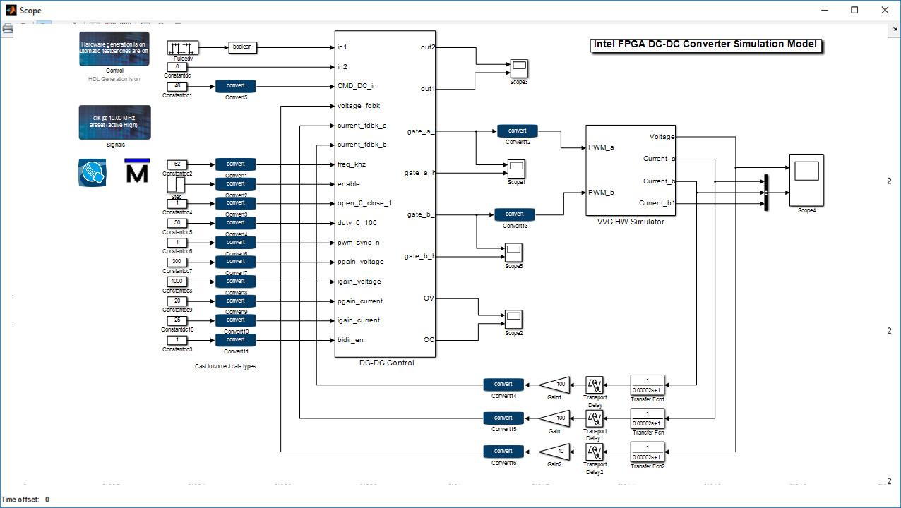
- lvdcdc_adsp_vhdl.slx is like lvdcdc_2phase_hwsim.slx but the algorithm is implemented using DSP Builder for Intel FPGAs so that you can generate HDL code.
Figure 31. DC-DC Converter Linear MATLAB ModelThe figure shows the linear MATLAB model (lvdcdc_simpower.slx). The linear model cannot generate VHDL, but you create it to provide a rapid simulation to develop control dynamics and determine controller gains.
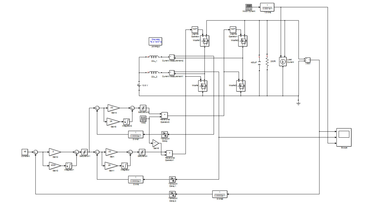
Figure 32. DC-DC Converter: DC bus Voltage, Inductor Currents, Motor Load Current (stimulus)The figure shows the linear MATLAB model (lvdcdc_simpower.slx) and simulation.
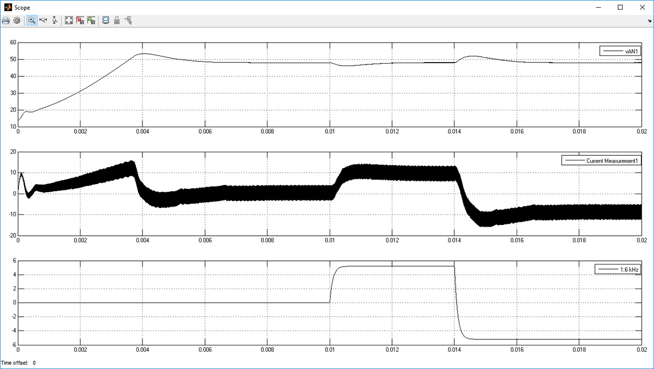
Figure 33. DSP Builder for Intel FPGAs Top-level ModelThe DSP Builder for Intel FPGAs model (lvdcdc_adsp_vhdl.slx) performs the same simulation as above, but includes DSP Builder for Intel FPGAs blocks that allow simulation of VHDL and auto-generation of VHDL code.