Video and Vision Processing Suite Intel® FPGA IP User Guide

ID 683329
Date 4/03/2023
Public

A newer version of this document is available. Customers should click here to go to the newest version.

Document Table of Contents
1. About the Video and Vision Processing Suite 2. Getting Started with the Video and Vision Processing IPs 3. Video and Vision Processing IPs Functional Description 4. Video and Vision Processing IP Interfaces 5. Video and Vision Processing IP Registers 6. Video and Vision Processing IPs Software Programming Model 7. Protocol Converter Intel® FPGA IP 8. 3D LUT Intel® FPGA IP 9. AXI-Stream Broadcaster Intel® FPGA IP 10. Chroma Key Intel® FPGA IP 11. Chroma Resampler Intel® FPGA IP 12. Clipper Intel® FPGA IP 13. Clocked Video Input Intel® FPGA IP 14. Clocked Video to Full-Raster Converter Intel® FPGA IP 15. Clocked Video Output Intel® FPGA IP 16. Color Space Converter Intel® FPGA IP 17. Deinterlacer Intel® FPGA IP 18. FIR Filter Intel® FPGA IP 19. Frame Cleaner Intel® FPGA IP 20. Full-Raster to Clocked Video Converter Intel® FPGA IP 21. Full-Raster to Streaming Converter Intel® FPGA IP 22. Genlock Controller Intel® FPGA IP 23. Generic Crosspoint Intel® FPGA IP 24. Genlock Signal Router Intel® FPGA IP 25. Guard Bands Intel® FPGA IP 26. Interlacer Intel® FPGA IP 27. Mixer Intel® FPGA IP 28. Pixels in Parallel Converter Intel® FPGA IP 29. Scaler Intel® FPGA IP 30. Stream Cleaner Intel® FPGA IP 31. Switch Intel® FPGA IP 32. Tone Mapping Operator Intel® FPGA IP 33. Test Pattern Generator Intel® FPGA IP 34. Video Frame Buffer Intel® FPGA IP 35. Video Streaming FIFO Intel® FPGA IP 36. Video Timing Generator Intel® FPGA IP 37. Warp Intel® FPGA IP 38. Design Security 39. Document Revision History for Video and Vision Processing Suite User Guide

29.3.1. Coefficient Selection

If you select polyphase scaling for the Scaler IP, the coefficients that the scaling filters use are read from a memory. You must define the contents of this memory. Either specify fixed horizontal and vertical coefficient sets in the Horizontal coefficient function and Vertical coefficient function parameters or turn on Update coefficients at runtime. If you turn on Update coefficients at runtime, you can write whatever values you want to the coefficient memory. If you already have well defined coefficient sets that you use, the flexibility in the scaler to select the desired number of filter taps and phases should allow you to continue with these. If you are new to scaling, read the following guidance on coefficient selection.

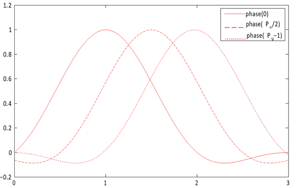
Generally, the set of coefficients that the IP writes to filter phase 0 yield a low-pass filter, with most weight in generating the output pixel value given to the pixel value in tap . The function is centered at tap . The coefficients the IP writes to the other phases are then just phase-shifted versions of this function (hence the name phase for each coefficient address), with the function centered at a point that is shifted by 1/ num_of_pixels of a pixel with every subsequent phase.

Figure 62. 2-lobe Lanczos function at 3 different phases This figure shows an example of how a function is progressively phase-shifted to create the coefficients for each scaling filter phase. The figure shows a 4 tap filter, with the taps shown on the x-axis

The Lanczos function is a common function that defines scaling coefficients. The Lanczos function is a base sinc function, with the primary lobe of a sinc function used as a window function to preserve a given number of lobes of the base sinc. The number of lobes is generally appended to Lanczos when referring to a specific variant of the function, so a Lanczos function where two lobes are preserved is referred to as Lanczos2. In the case where N lobes are preserved, the LanczosN function is defined as:

Equation 8. Coefficient Selection Equation

When using LanczosN coefficients, Intel recommends configuring the scaler filters with the following numbers of taps for the upscale and downscale cases:

  • Upscale: 2 × N
  • Downscale:

The number of lobes in the Lanczos function affects the frequency response of the filter and, as a result, the quality of the image produced. Generally, Lanczos functions with lower numbers of lobes give a softer frequency response and a resulting image with more blur on the edges, but with less risk of ringing artifacts in the areas immediately around the edges. Conversely, Lanczos functions with higher numbers of lobes give sharper edges but introduce more ringing artifacts. Lanczos2 is a good compromise between minimizing blur and minimizing ringing, but you can experiment with Lanczos3 or Lanczos4 to make your own judgment. The higher the number of lobes, the more filter taps (and therefore FPGA device resources) the design requires to implement the filter correctly. You should experiment with Lanczos1 coefficients for large downscales.