A newer version of this document is available. Customers should click here to go to the newest version.
1. Overview
2. Quick Start Guide
3. Configuring and Generating the GTS AXI Multichannel DMA IP for PCI Express
4. Integrating the IP With Your Application
5. Simulating the IP
6. Validating the IP
A. Appendix A: Functional Description
B. Appendix B: Registers
C. Document Revision History for the GTS AXI Multichannel DMA IP for PCI Express*
2.1.1. Downloading and Installing Quartus® Prime Software
2.1.2. Configuring and Generating the GTS AXI Multichannel DMA IP for PCI Express
2.1.3. Configuring and Generating the GTS AXI Streaming Intel FPGA IP for PCI Express
2.1.4. Configuring and Generating the GTS System PLL Clocks Intel FPGA IP
2.1.5. Configuring and Generating the GTS Reset Sequencer Intel FPGA IP
2.1.6. Configuring and Generating the Reset Release IP
2.1.7. Instantiating and Connecting the IP Interfaces
2.1.8. Simulate, Compile and Validate the Design on Hardware
4.4.1. PCIe AXI-Stream TX Interface (ss_tx_st)
4.4.2. PCIe AXI-Stream RX Interface (ss_rx_st)
4.4.3. Control and Status Register Interface (ss_csr_lite)
4.4.4. Transmit Flow Control Credit Interface (ss_txcrdt)
4.4.5. Configuration Intercept Interface (CII)
4.4.6. Completion Timeout Interface (ss_cplto)
4.4.7. Function Level Reset (FLR) Interface
4.4.8. Control Shadow Interface (ss_ctrlshadow)
4.4.9. Error Interface
4.5.1. H2D AXI-Stream Manager (h2d_st_initatr)
4.5.2. D2H AXI-Stream Subordinate (d2h_st_respndr)
4.5.3. H2D/D2H AXI-MM Manager (dma_mm_initatr)
4.5.4. BAM AXI-MM Manager (bam_mm_initatr)
4.5.5. BAS AXI-MM Subordinate (bas_mm_respndr)
4.5.6. PIO AXI-Lite Manager (pio_lite_initiatr)
4.5.7. HIP Reconfiguration AXI-Lite Subordinate (user_csr_lite)
4.5.8. User Event MSI-X (user_msix)
4.5.9. User Event MSI (user_msi)
4.5.10. User Function Level Reset (user_flr)
4.5.11. User Configuration Intercept Interface
4.5.12. Configuration Slave (cs_lite_respndr)
A.1.1.1. H2D Data Mover
A.1.1.2. D2H Data Mover
A.1.1.3. Descriptors
A.1.1.4. AXI4-Lite PIO Manager
A.1.1.5. AXI-MM Write (H2D) and Read (D2H) Manager
A.1.1.6. AXI-Stream Manager (H2D) and Subordinate (D2H)
A.1.1.7. User MSI-X
A.1.1.8. User Function Level Reset (FLR)
A.1.1.9. Control and Status Registers
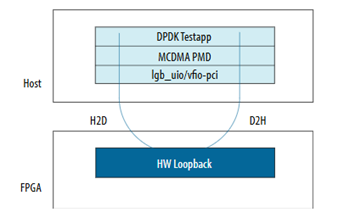
6.2.7.3.1. Device-side Packet Loopback
The DPDK driver can also be used with the AXI-S Device-side Packet Loopback design example for loopback test.
The following diagram shows the testing strategy.
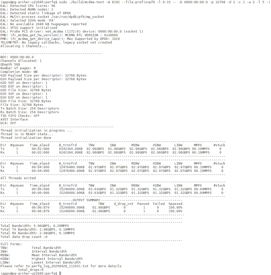
Complete the instructions outlined in Prerequisites before running the following command for the loopback test:
$ ./build/mcdma-test -m 8192 --file-prefix=pf0 -l 0-15 -- -b 0000:01:00.0
-p 32768 -d 2 -c 1 -a 2 -l 5 -i
Configuration:
- Memory allocation size (-m 8192)
- Physical function number (--file-prefix=pf0)
- Number of CPU cores allocated for the test (-l 0-15), to match the output from the "sudo lscpu | grep NUMA" command
- BDF (-b 0000:01:00.0)
- 1 DMA channel (-c 1)
- Bidirectional H2D-D2H Loopback (-i)
- Payload length of 32,768 bytes in each descriptor (-p 32768)
- Transfer the data for 5 seconds (-l 5)
- Dump the progress log every 2 seconds (-d 2)
- Total of two threads (-a 2)
- Transfer data for 5 seconds (-l 5)
Configuration for AXI-S LB Undefined single function mode in examples/mcdma-test/perfq/meson.build .
-UIFC_MCDMA_SINGLE_FUNC
Command for loopback:
./build/mcdma-test –m 16384 –l 0-8 - -b -p 64 -l 2 -i -d 1 -c 2048
Note: In the current release, a single page is supported in DIDF mode.
Note: In the current release, a simultaneous process is not supported in DIDF mode. You can run one process with 2K channels.