A newer version of this document is available. Customers should click here to go to the newest version.
4.1.5. Clock Connections in Synchronous Ethernet Operation (Sync-E)
When you enable the Synchronous Ethernet (SyncE) operation, two or more channels can share the off-chip cleanup PLL clock output. The Synchronous Ethernet standard, described in the ITU-T G.8261, G.8262, and G.8264 recommendations, requires that the TX clock be filtered to maintain synchronization with the RX reference clock through a sequence of nodes. The expected usage is that user logic drives the transceiver reference clocks with a filtered version of the RX recovered clock signal, to ensure the receive and transmit functions remain synchronized. In this scenario, a design component outside the IP performs the filtering process.
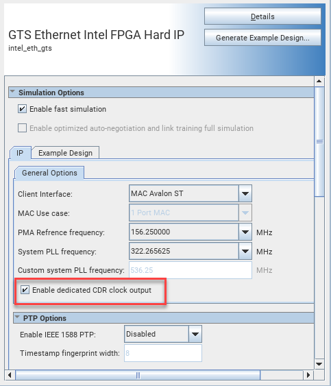
The following figure shows an alternate clocking arrangement for the transceiver reference clock that can be used to enable SyncE operation. the recovered clock outputs o_clk_rec_div or o_clk_rec_div64 or o_cdr_divclk from the GTS Ethernet Intel® FPGA Hard IP can be connected to the off-chip cleanup PLL using REFCLK_GTS pin. In GTS, the dedicated clock output (o_cdr_divclk) from the PMA can be driven to local reference clock pin or dedicated clock output pins if the device has single transceiver bank, whereas the clocks o_clk_rec_div64 and o_clk_rec_div are available at GPIO pins.

Two or more channels share the clock output of an Off-chip Cleanup PLL that meets the specification for a SyncE link. The FPGA provides a primary SyncE clock and a backup SyncE clock to the cleanup PLL. The primary and backup cleanup clocks come from recovered clock output pins from a pair of channels that are both connected to remote stations connected to the same SyncE network, with the transceiver reference clock sourced from the output of the cleanup PLL.
The output frequency is equal to the nominal incoming refclk divided by any predivider on the RX path. The following table shows the recovered clock frequencies with respect to input reference clock.
| i_clk_ref((MHz) | N Divider | o_cdr_divclk(MHz) |
|---|---|---|
| 156.25 | 4 | 39.0625 |
| 312.5 | 4 | 78.125 |
| 322.265625 | 4 | 80.5664 |