F-tile Architecture and PMA and FEC Direct PHY IP User Guide
A newer version of this document is available. Customers should click here to go to the newest version.
2.4.4. Datapath Clock Cadences
The read and write frequency of the PMA FIFO interface determines if you need a standard or custom cadence.
- Standard cadence: Use if the read and write frequencies of the PMA FIFO interface are the same with 0 ppm frequency delta.
- Custom cadence: Use if the read and write frequencies of the PMA FIFO interface have different frequencies or have the same frequency but with a frequency delta of greater than 0 ppm.
See PMA Data Rates for supported data rates.
| Datapath Clocking Mode | Configuration | Datapath Clock Frequency | Cadence |
|---|---|---|---|
| PMA clocking mode (maximum 906.25 MHz) |
PMA Direct | Datapath clock frequency = PMA clock frequency PMA clock frequency = line rate ÷ PMA width |
Use the standard cadence on the TX and RX (data is valid at every clock edge). 15 |
| System PLL clocking mode (maximum 1 GHz) |
PMA Direct | Use Case A: Chip-to-chip applications where F-tile and link partner share the same reference clock Datapath clock frequency ≥ (system PLL output frequency)min where (system PLL output frequency)min = PMA clock frequency |
If (system PLL output frequency = PMA clock frequency and ∆ppm = 0), use the standard cadence on the TX and RX (data is valid at every clock edge). Otherwise, use custom cadence. 16 , 17 |
| Use Case B: Applications where F-tile and link partner do not share the same reference clock Datapath clock frequency ≥ (system PLL output frequency)min where (system PLL output frequency)min = (maximum ppm 18 ÷ 1000000 + 1) × PMA clock frequency |
|||
| System PLL clocking mode (maximum 1 GHz) |
Other configurations with FEC, PCS, and MAC | Datapath clock frequency ≥ (system PLL output frequency)min where (system PLL output frequency)min = PMA clock frequency For example, for 10GbE-1, use ≥ 322.265625 MHz; for 25GbE-1, use ≥ 805.6640625 MHz; and, for 50GbE-1, use ≥ 830.078125 MHz. |
If (system PLL output frequency = PMA clock frequency), use the standard cadence on the TX and RX (data is valid at every 32 of 33 or 34 clock cycles). Otherwise, use custom cadence. 19 |
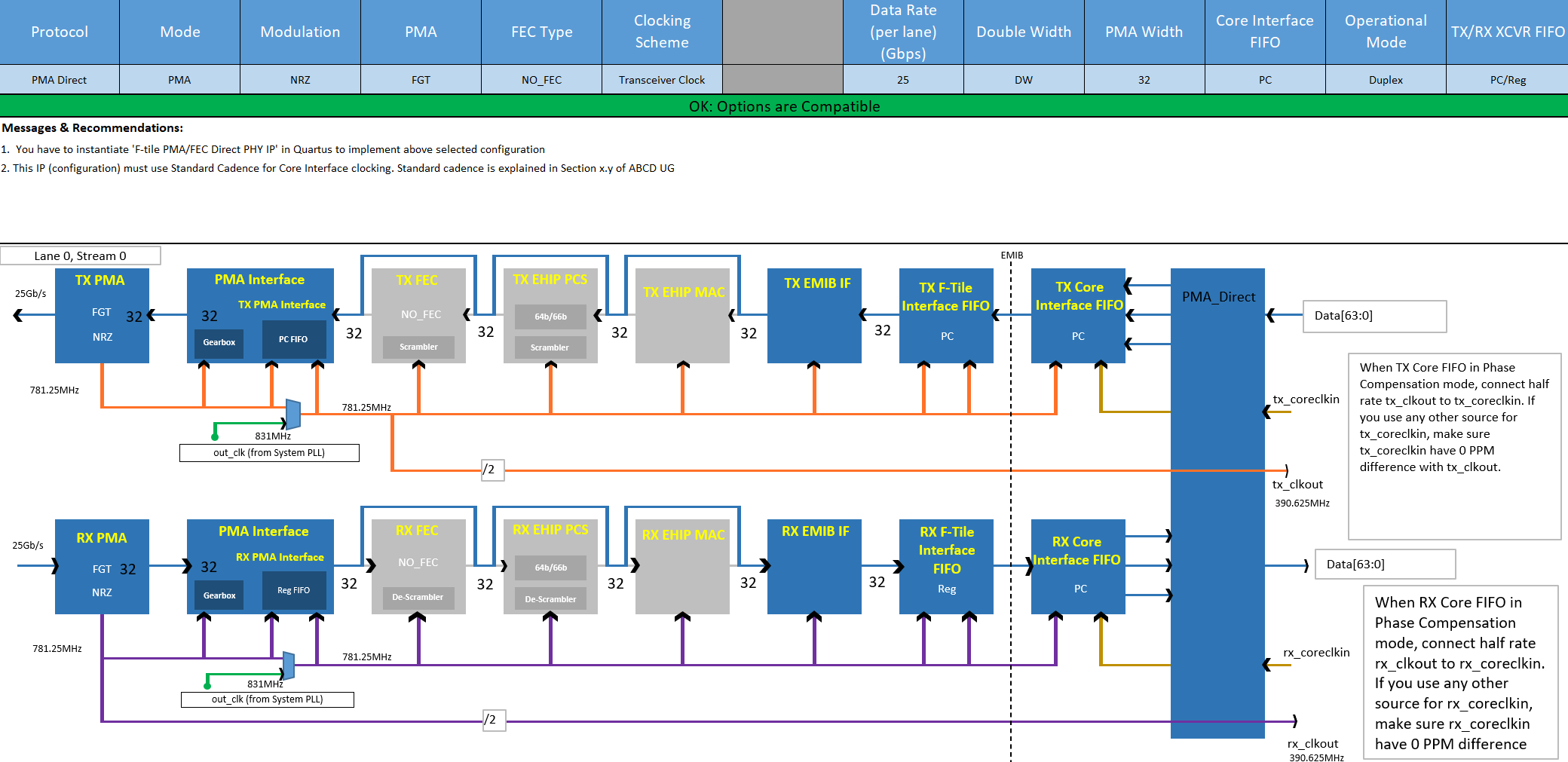
One 25 Gbps PMA Direct PHY IP Port Using the PMA Clocking Mode Example
- All blocks between the PMA interface and core FIFO interface run on the PMA clock.
- On the transmitter, the PMA FIFO interface is clocked by the TX PMA clock on both sides.
- On the receiver, the PMA FIFO interface is clocked by the RX recovered clock on both sides.
- Use the standard cadence. Data on the TX and RX is valid at every clock edge of the PMA clock.
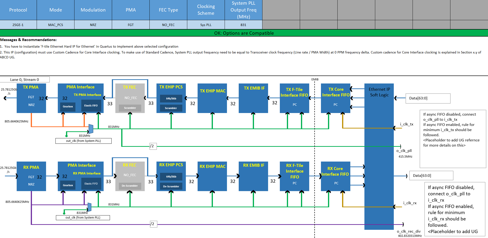
25 Gbps Ethernet Without FEC Port Using the Overclocked System PLL Clocking Mode Example
- All blocks between the PMA interface and core FIFO interface run on the system PLL clock.
- On the transmitter, the PMA FIFO interface performs a clock transfer from the system PLL domain to the TX PMA clock domain.
- On the receiver, the PMA FIFO interface performs a clock transfer from the RX recovered clock domain to the system PLL domain. Refer to F-Tile Ethernet Intel® FPGA Hard IP User Guide for how to clock the core interface.
- Because the system PLL clock frequency is faster than the PMA clock frequency, datapath clocking is overclocked. Therefore, you must use custom cadence.
maximum ppm = maximum ∆ppm ÷ 2
maximum ∆ppm = max(∆ppm between the link partner TX (the recovered clock on the local RX) and system PLL, ∆ppm between the system PLL and TX PMA)