F-Tile Avalon® Streaming Intel® FPGA IP for PCI Express* User Guide
A newer version of this document is available. Customers should click here to go to the newest version.
4.3. Precision Time Measurement (PTM)
Precision Time Measurement (PTM) enables precise coordination of events across multiple components with independent local time clocks. Ordinarily, such precise coordination would be difficult given that individual time clocks have differing notions of the value and rate of change of time. To work around this limitation, PTM enables components to calculate the relationship between their local times and a shared PTM Master Time: an independent time domain associated with a PTM Root. Each PTM Root supplies PTM Master Time for a PTM Hierarchy.
PTM Requester refers to a function capable of using PTM as a consumer associated with an Endpoint or an Upstream Port. PTM Responder refers to a function capable of using PTM to supply PTM Master Time associated with a Root Port or Root Complex. PTM Root is the source of PTM Master Time for a PTM Hierarcy and also a PTM responder. F-Tile PCIe Hard IP supports PTM in endpoint mode or PTM Requester.
- PTM is implemented only as EndPoint mode (PTM Requester) for F-Tile.
- Port 0 or Port 1 configuration as EndPoint mode is capable of PTM support. Only 1 port can enable PTM feature at anytime.
The PTM Requester of F-Tile PCIe Hard IP automatically updates PTM context (starting dialogs) when enabled. It can be configured to be automatic trigger every 1 ms to 10 ms or manual trigger through user input only.
The figure above show the timing diagram for PTM interface when the automatic triggers enabled. ptm_context_valid_o indicates if the ptm_local_clock_o is valid.
- Clock stops or runs at the wrong frequency (for example, when the link speed is changing), or
- PTM is disabled, or
- PTM response timeouts (the requester restarts the PTM dialog when the auto update or manual update start conditions are met), or
- A duplicate PTM TLP is received or a replay TLP is sent (if waiting for a response the requester waits for 100 μs since the last non-duplicate request was sent, before allowing a new PTM dialog to be started.
The received PTM messages will also be forwarded out to the application layer.
When using PTM between two components on a PCIe link, the Upstream Port, which acts on behalf of the PTM Requester, sends PTM Requests to the Downstream Port on the same Link, which acts on behalf of the PTM Responder as you can see in the figure above.
The points t1, t2, t3, and t4 represent timestamps captured locally by each Port as they transmit and receive PTM Messages. The component associated with each Port stores these timestamps from the 1st PTM dialog in internal registers for use in the 2nd PTM dialog, and so on for subsequent PTM dialogs.
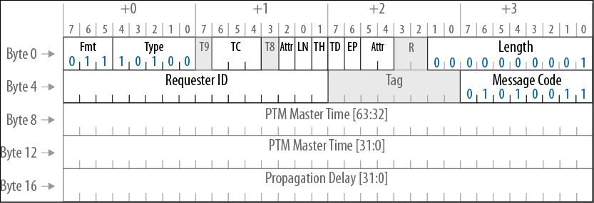
In the 2nd PTM dialog, the Downstream Port populates the PTM ResponseD message based on timestamps stored during previous PTM dialogs, the format is shown in the second figure below. It contains PTM Master Time which is t2’ and propagation delay which is t3-t2.
The component associated with the Upstream Port can then combine its timestamps with those passed in the PTM ResponseD message to calculate the PTM Master Time using the formula here: PTM Master Time at t1’= t2' - [((t4-t1) - (t3-t2))/2]