1.2.1. Understanding the Different PTP Clocks
1.2.2. Precision Time Protocol (PTP) Synchronization Process
1.2.3. Functional Flow For A 1588 Ordinary Clock Master/Slave Mode System
1.2.4. Functional Flow For A 1588 Transparent Clock Master/Slave Mode System
1.2.5. Functional Flow for A 1588 Boundary Clock Mode System
1.2.6. Timestamp Packet Functional Flow in Linux Driver
1.3.2.2. Executing The Reference Design
This section shows step by step guide to execute the reference design on the Altera Arria V SoC Development Board.
- Login to the system on both Board A and Board B.
- Assign IP address for Board A.
ifconfig eth0 10.0.0.1 netmask 255.255.255.0 up
- Assign IP address for Board B.
ifconfig eth0 10.0.0.2 netmask 255.255.255.0 up
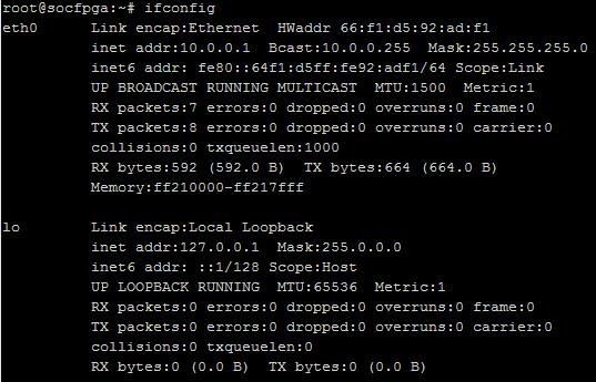
- Type ifconfig to check the IP addresses are successfully assigned to Board A and Board B.
The following figure shows a screen capture for a successful IP address assignation.Figure 16. Successful IP Address Assignation
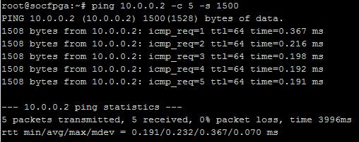
- Test the network connectivity between the two boards by using ping command to the assigned IP addresses.
Example: Type ping 10.0.0.2 from Board A.Type ping 10.0.0.1 from Board B.The following figure shows successful connections between the two boards.Figure 17. Successful Connection Screen Capture
- You can check the Altera 10G-bps Ethernet MAC register values and statistics using the following commands.
Use ethtool -S eth0 to view statistic counters.Use ethtool -d eth0 to view MAC register settings.
- You can use the Ptp4l software in the LinuxPTP package to measure the timestamp accuracy of the reference design. By default, the hardware timestamping is selected and time interval between SYNC messages is set to 1 second.
- Use testptp -c to view the PTP hardware clock capabilities on both boards.
- Use ethtool -C eth0 tx-frames 1 command to send packet to the stack without any delay on both boards. This must be done before executing ptp4l command.
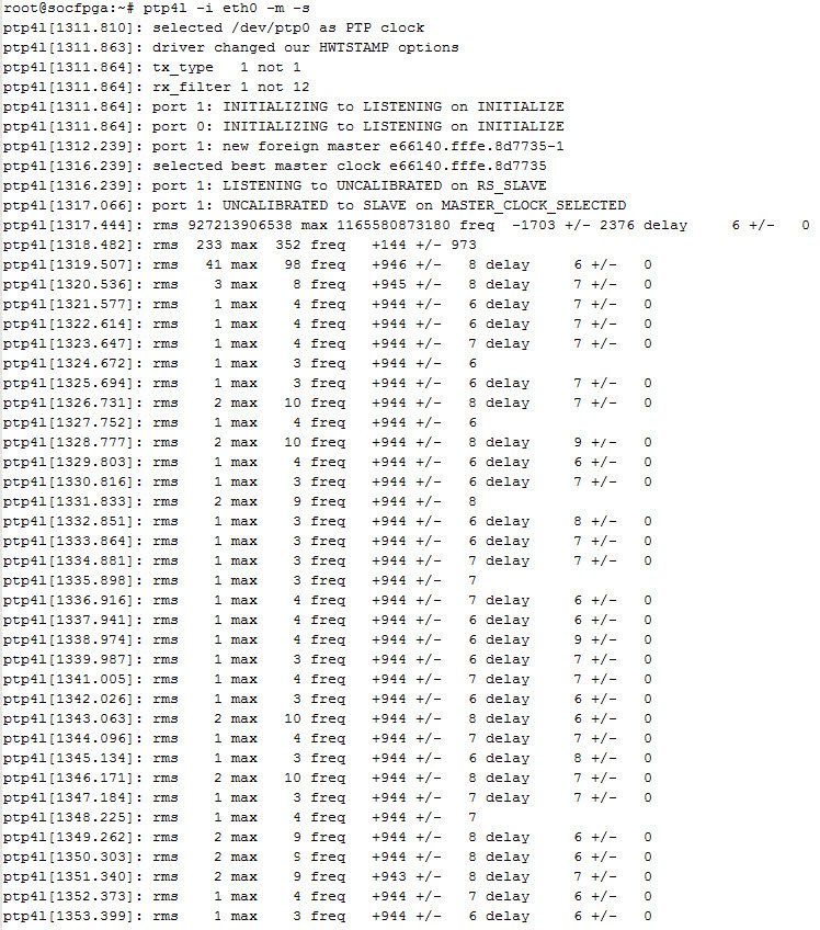
- Type ptp4l -i eth0 -m to start a PTP Master on Board A with the IP address of 10.0.0.1.
- Type ptp4l -i eth0 -m -s to start a PTP Client on Board B with the IP address of 10.0.0.2. The PTP measurement starts at this point.
- Stop the PTP measurement on Board B (PTP client) by pressing CTRL + C on your keyboard.
- Type testptp -f 0 to reset the MAC clock period default to 6.4ns on Board B (PTP client) after the measurement has stopped.
- Optionally, type testptp -s to reset PTP hardware clock time to system time at PTP client.
- By default, the PTP Master sends 1 SYNC message per every second. You can create a configuration file to override the default settings of ptp4l. The following code shows the example of ptp4l configuration file to set PTP Master to send 512 SYNC messages every second. This setting provides a timestamp accuracy of 6.99ns for every 100 samples.
[global]logSyncInterval -9
- Type ptp4l -i eth0 -m –f <filename> to re-start the PTP Master board with the new configuration file.
The following figure shows the example PTP4L measurement log. The average timestamp accuracy demonstrated in this reference design is calculated based on the following equation:Average timestamp accuracy = sum of max offset / number of data samplesNote: where max offset and number of data samples are only referring to the high values observed during the PTP measurement.Figure 18. Example of PTP4L Measurement Log
Related Information